")
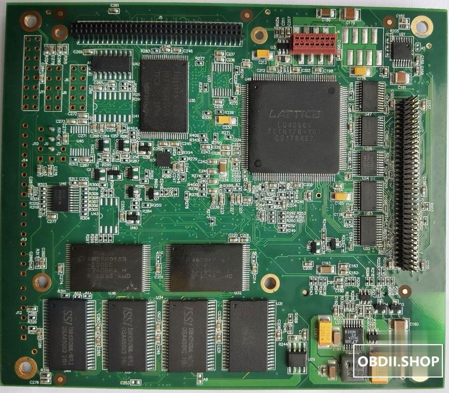
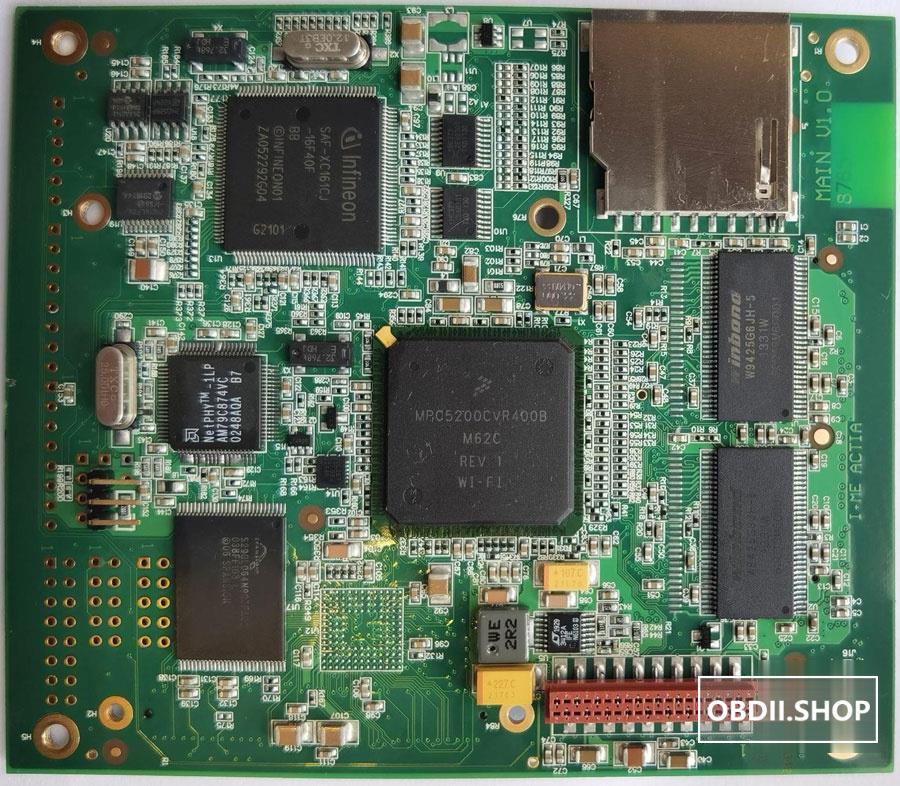
This will focus on board and component level repairs including charging circuitry, overheating issues, UART and DCDI 201 errors, as well as replacing and flashing chips such as the XC161 and LC4256V. You should be able to repair any c4/c5 or even build your own if you can get the PCB schematics.
In the context of our MB SD C4 clones:
MPC/SPC5200B CPU – always used salvage, some re-marks. some are even MPC5200 re-marked as MPS5200B (still kinda works)
XC161CJ – always salvaged and re-marks. lots of problems with these.
LC4256V – always salvaged, some are re-marked. they do go pop.
RAM and Flash – Mostly salvaged, some re-marks but you can get lucky (or really unlucky).
Tantalum caps – Always salvaged or fakes. critical to change if you can
E-Caps – some are ok, most are rubbish
IRF5210S – almost always re-marked salvage or fakes
FDD5614P – lottery, I’ve seen both real, re-marked and fakes
LT DC power chips (LT3434, 3412 and 1976) – always salvaged, some are re-marks
CAN chips (TJA104x and 105x) – almost always re-marks
PIC chips – always re-marked salvage, but they dont go bad often.
DG406/ADG426 – salvaged, with the ADG426 are always re-marks as they are expensive
LM2936DT5.0 – re-marks, most are using the LM78M05 as a replacement instead. Not ideal, but it works.
LL014N – salvaged and re-marks
BSP75N – salvaged and re-marks
Relays – salvages and re-marks, some more expensive C4 clones can have genuine, new relays.
list goes on….. and on….
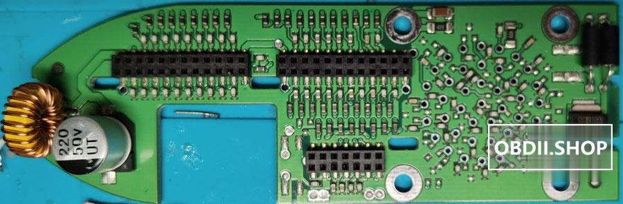
So, with the exception of the SOT23 diodes, SOT23 transistors (847 and 857), passive components such as resistors and ceramic capacitors, everything else is saved. Even the crystals and oscillators are recovered. It’s actually a miracle that so many of these units actually work. Here are some beauty shots of one of the fully redesigned C4s.
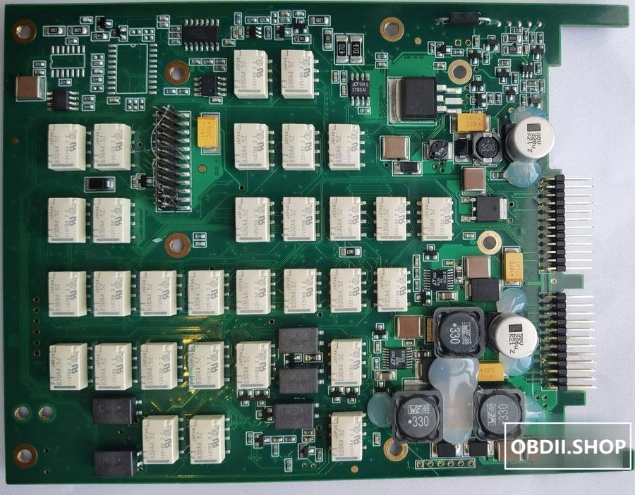
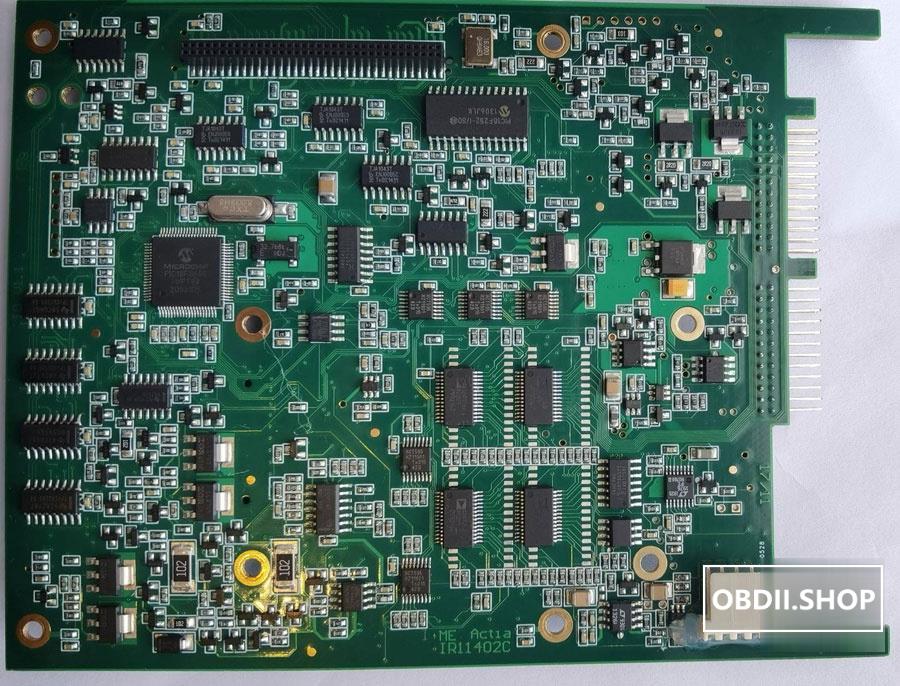
For the more familiar C4’s there’s 4 PCBs, the LAN, Sideboard, I/O and Logic. The DOIP version has one more, the DOIP board.
First up the LAN PCB.
LAN PCB:
There’s 2 main types, DOIP and the normal with the normal type showing up in many versions but just respins of the same circuit so functionally identical. There’s a third type which has no components on it but with 4 header pins to allow a Wifi module to hang off it, marketed as XC4. We’ll talk about those another time.
DoIP
Normal
The main difference is the MB SD C4 DOIP version uses a 12pin AMP Micromatch connector. The extra 4 pins are there for power as I believe the DOIP version can be charged via the ethernet port. Great you say…. But no, the clones didn’t use the super expensive and rare Yamaichi Y-Con RJ45 with DC contacts for charging; so its never gonna happen for us clone users even if you repopulate the missing fuses and get the right plugs etc.
For the normal LAN PCB, there’s nothing much to write about. The ethernet magnetics often have its marking filed off as if its some super secret. It always makes me smile and tells me the producers are just producers, they don’t have any idea about electronics and what they are doing. Thieves worried about other thieves copying LOL.
Common to both types of LAN PCB are the shitty black plastic molding for the RJ45. It’s a pain in the butt. The clones tried to mimic the original’s special latching mechanism for the industrial ethernet cable (I’m not able to find any data on this so may be the cable latch is custom?). In any case the plastic used to over-mold the RJ45 socket is rubbish, it cracks and breaks if you just look at it the wrong way. Do not try to tighten it to the metal plate, be gentle and use thread-locker (loctite) instead.
As an aside in my investigations the distance between the two mounting holes are the same as the Harting PushPull industrial ethernet connectors but I couldn’t make it work because some required inserts (keystones) are no longer manufactured by harting in order to maintain the C4’s splash resistance rating when disconnected. In my PoE mod I’ll be using a mil-spec bayonet ethernet connector instead.
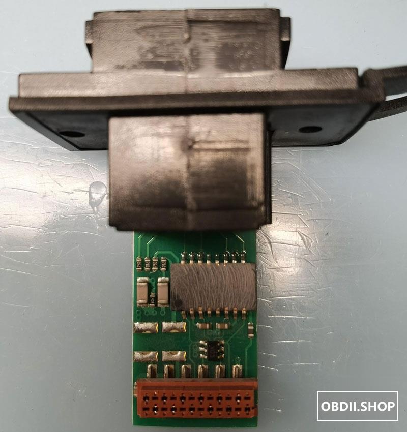
The Sideboard:
There’s basically 2 types, Normal and DOIP, and they are both shit and are total train wrecks as we’ll see in this post. Here are the pictures without the 38pin ECTA 133 socket.
Normal
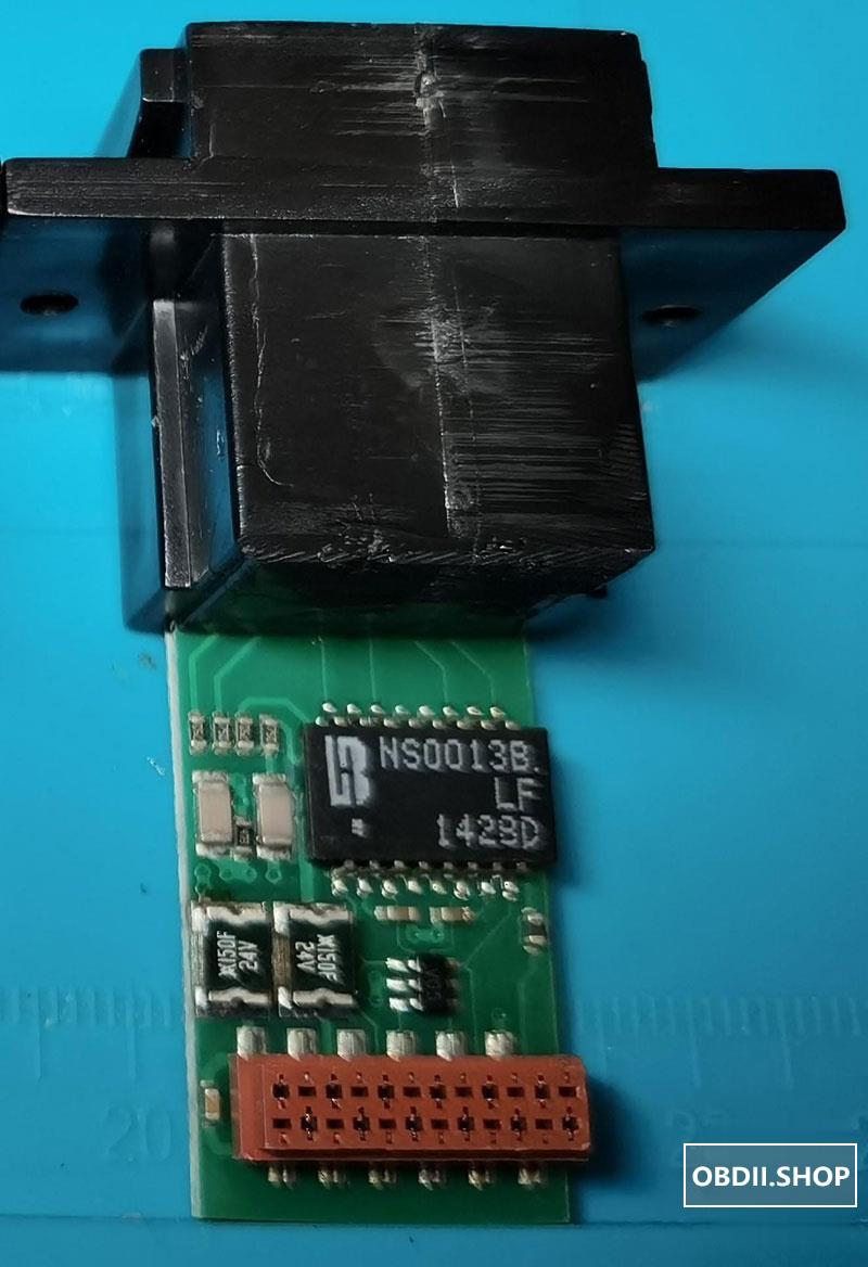
DoIP
The DOIP Sideboard uses a different DPAK power diode. It uses a 2-way diode bacause it can draw power from both the 38pin ECTA and ethernet ports.
As you can see in the pictures, in addition to many missing components; staring at us in the face are, in my opinion, the reasons why the clone C4’s tend to self destruct. Over the years each successive clone revisions had skimmed more and more on the protection circuitry. In addition to missing components, are just plain wrong components being used. Out of the 7 C4’s I’ve played with NONE have component values anywhere close to being able to protect the C4. I cannot believe no one has written about this in the past.
If your C4 doesn’t have even the most basic protections, its going to blow and cause expensive or terminal damage when something do go wrong. This is even before we talk about EMI which evidently the producers did not care one iota about.
Fuses
I have seen fuses ranging from 2A to 15A, some are even bridged (no fuse). The fuses seems to be random picks from the bin. I believe a good value is 2A fast blow as I have never seen the C4 draw more than 1.4A peak even while charging its batteries. Most of the time it draws less than 500mA. The key here is that a 2A input fuse will make sure your C4 don’t burn out PCB traces when something blows (hint – fake tantalum caps loves doing that, and they tend to fail short). I used Littel fuse or Bel, beware there are fake Littel Fuse everywhere and you can’t test them, well you can, but they are useless afterwards. DO THIS!
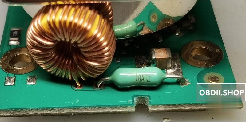
Fuse 10A
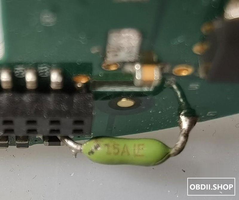
Fuse 15A
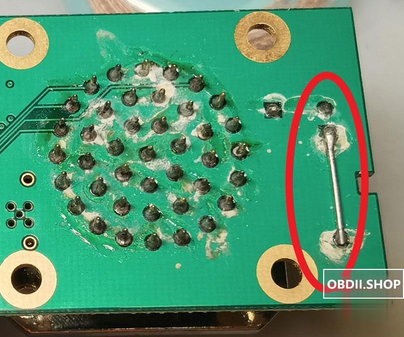
Fuse short
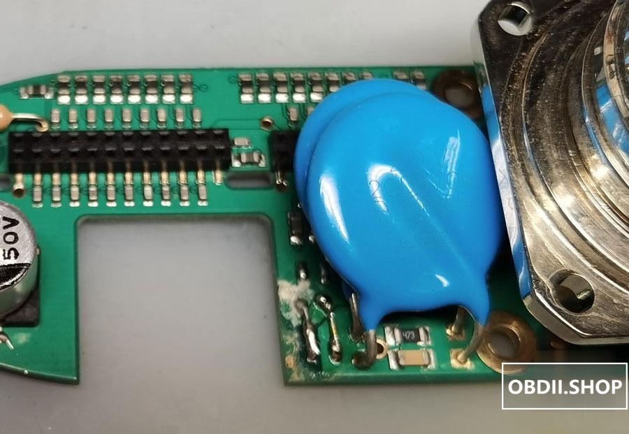
MOV
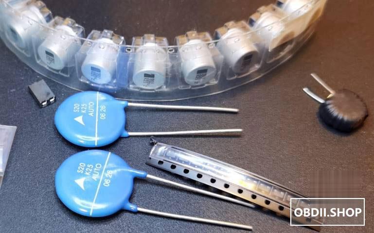
NONE of the C4’s I’ve seen had the right MOV. Most are 390V or 470V! One has a 47V (better, but still wrong). So it seems the MOV used in the clone C4’s were pulled from domestic AC appliances! But what voltage should we see on these VCI’s? 24V nominal on trucks and if you see anything higher something is seriously wrong!
So IMO a 24V-ish MOV should be used. I am using the Epcos S20K25 or 30 for 25V and 30V depends on whether I care about working on trucks (but both should work on trucks). The 391 and 471 MOV as seen below will do absolutely nothing to protect your C4 when there’s a high voltage coming from the external power. DO THIS!
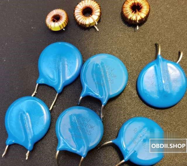
Random collection of wrong Inductors and MOV from C4 Clones
TVS
NONE of the C4 Clone sideboards have the SOT23 package TVS diodes installed. Again, if there are any ESD events coming down the OBD cable its going straight into the C4’s front end. There are many options but I am using the NUP2105L, it’s a dual 2-way 27V TVS. DO THIS!
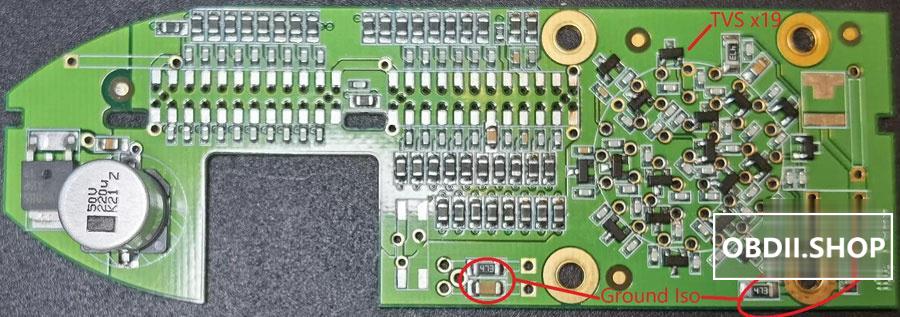
There’re 19 of these bad boys!
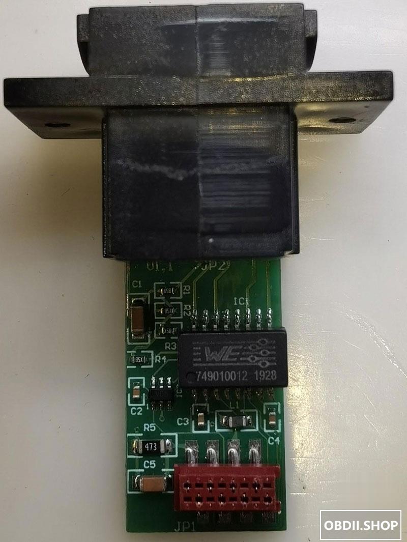
CMS Bead Array
I have seen exactly ONE C4 clone (an early one) that had this installed. The CMS bead array helps filter the input power and stops EMI ringing. Its mostly EMI related and not strictly necessary for our purposes (your C4 is working right?) but if you’re going to rework it, put it on (WE 7427521). BUT…..
Be careful on the version of your sideboards. The early non-DOIP ones that didn’t have the bead array installed would have the component pads bridged with wires, for those it’s easy enough to remove them before installing the real thing.
Bridged hack
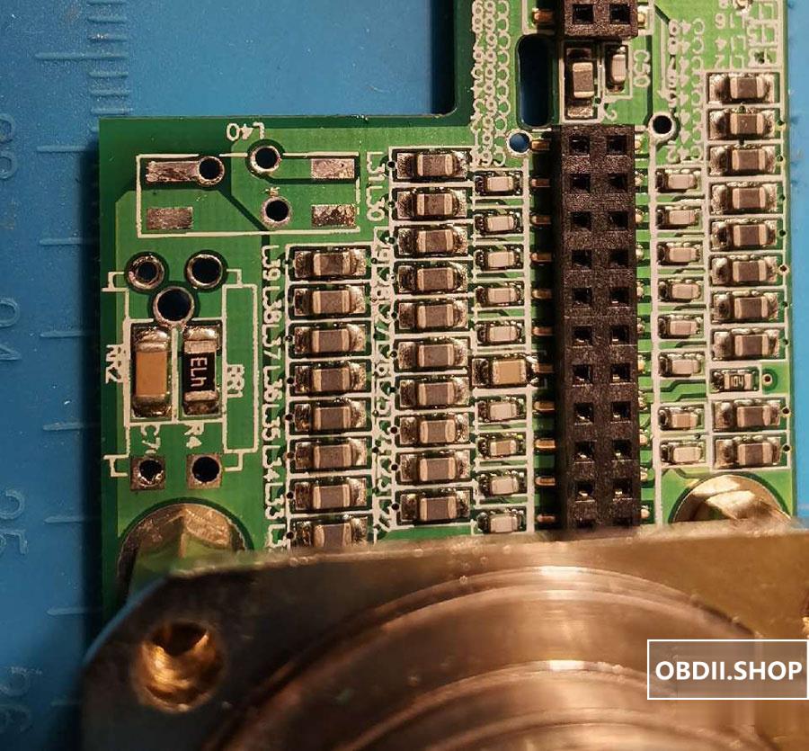
Bridge removed, good PCB traces for retrofit
However, the later revisions have new PCB traces baked-in to make the jumper unnecessary, in which case you need to cut 2 traces before you put on the bead array.
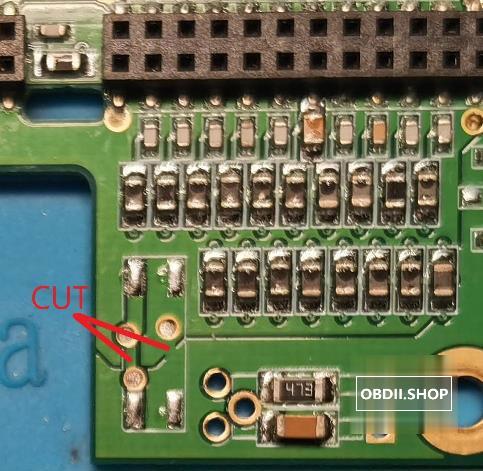
Where to cut if retrofitting the bead array
For all the DOIP version I have here the situation is even worse. The PCB trace we need to cut is actually buried in the multilayer board, which means without knowing the actual PCB schematic or destroying a few PCBs to find out, its almost impossible to retrofit the bead array. If I had to guess its just between the 2 via’s but I’m not going to destory the board to find out as I don’t have any spares. I have installed the bead array on mine anyway to satisfy my OCD, knowing it will do nothing.
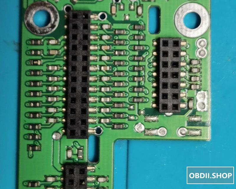
No idea where to cut, buried in the PCB
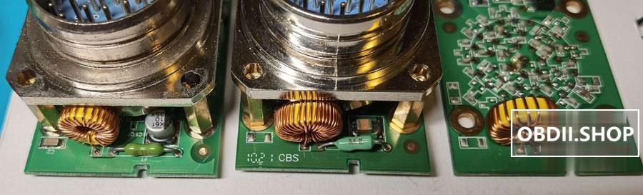
Inductor and Cap
On most C4 clones the inductor seems to be random, there are big ones and small ones, thick ones and thin ones with 10uH to 40uH being measured. Without an original C4 to compare against I have settled on a 22uH 3A unit. For the Cap, its either missing, using a undersized unit or replaced with a cheap ECap. I am using the same MLCC 10uF 50V X7R 2220 size unit I used for the 7 on I/O board.
Random parts selection strikes again!
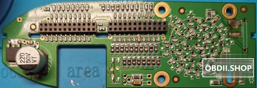
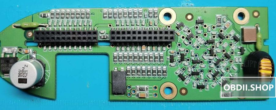
ECap
Not much to say here. If you’re doing so much work you might as well change the bulk cap out for a unit of known quality. I am using a 50V 220uF alu ECap (I have both Vishay and Panasonic), same as what I’ll be using for the I/O board. ESR not really a concern for these bulk caps but as I have some around so that what I used. On one of the DOIP units I have this ECap is missing altogether, bravo.
Gound Isolation
on some units the cap or the resistor or both are missing that isolates the PCB ground to the shell. The resistor is a 47k and the cap I used is 1uF, size is 3216. Again this is a guess as I don’t have a genuine unit to verify against. If you know better, let us know.
Rework
Rework on this PCB is straight forward. Pics of good components and fully reworked sideboards. The DOIP sideboard will look similar.
SB Comp 2
If nothing else, please do the 3 critical remediations above, especially the fuse. It will save your MB SD C4/C5.
Leave a Reply