
GM tech2 is famous scanner which can work for GM/ SAAB/ OPEL/ SUZUKI/ ISUZU/ HOLDEN Expert/ Australia Holden . The Vetronix Tech 2 comes with Authentic GM software and provides support for on-board diagnostics on all GM systems 1992 thru 2014.
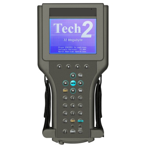
Tech 2 diagnostic scanner is composed of LCD screen, four “soft keys”, standard keyboard, vehicle communication interface module and RS-232 communication port. Different models can be tested by changing different plug-in cards.
Some customers dont know how to use it , actually its easy to use the scanner , lets check the operation steps as bellowing :
Step 1 : Turn on the power, the instrument enters the self-check state, and the screen performs “SYSTEM INITIANLIZING” for about 4 seconds; when the instrument emits a “beep”, the screen will display the version information of the instrument.
Step 2: Press Enter to enter the main menu, the screen displays: F0-Diagnosis, F1- Service Program System, F2- Display Captured Data, F3- Tool Options, F4-Enable.
Step 3: Use the up and down cursor keys to select the target and press the enter key to confirm.
Step 4 : Select the F0 function, enter the vehicle specification option, and select the model year by moving the cursor keys. Press the enter key to enter the vehicle system, select the appropriate type, and then press the enter key to enter the system selection menu, the screen displays: F0-engine power, F1-body, F2-chassis, F3-diagnostic circuit check.
Step 5: Move the cursor keys to select F0 and press Enter to enter the engine type option. At this time, you can choose 3.2L V6G8 or 3.1L V6L82. Choose the former and press Enter to directly enter the following functions; select the latter and press Enter After pressing the car key, you must select BUICK and press Enter to enter the following functions. The screen displays: F0- fault code (DTC), F1- data display, F2- special functions, F3- capture, F4-I/M information, F5 -ID information.
Step 6 : Select DTC and press Enter to enter the diagnostic code function: F0-DTC information, F1- failure record, F2- clear fault code, F3- capture information.
Step 7 : Move the cursor keys to select F0, press the Enter key to confirm, and enter the following interface: F0-DTC information, F1- view fault code (special DTC), F2- clear fault code and record, F3- diagnosis test description.
Step 8 : Move the cursor keys to select F0, press the Enter key to confirm, and the fault code will be displayed. Use the cursor keys to turn pages; or press the corresponding key of INFO to provide relevant help information.
Step 9 : Return to “7”, select F1, press Enter to confirm, and enter the fault query interface. At this time, you can enter the fault code to query the referred fault and provide relevant help information.
Step 10 : Return to “6”, select F1 and press Enter to confirm. At this time, the fault code can be displayed.
Step 11 : Return to “6”, select F2, press Enter to confirm, the screen prompts: Do you really want to clear it? (Y/N), press Y key to clear, press N key to cancel.
Step 12: Return to “6”, select F3, press Enter to confirm, the screen displays: Recapture information, repeat display, and prompt whether you want to refresh (Y/N), press Y to recapture, press N to repeat display.
Step 13: Return to “5”, select F2, press Enter to confirm, the screen displays: engine, transmission.
Step 14 : Move the cursor keys to select “Engine”, press Enter to confirm, and enter the following operation interface: F0- Engine number? Net? F1- Catalyst data, F2-EGR valve data, F3- Oxygen sensor data, F4- Instrument data , F5- ignition data, F6- output driver data, F7- canister data.
Step 15 : Move the cursor keys to select F0 engine data, and press Enter to enter the following interface: engine speed, ideal idle speed, water temperature, intake air temperature, air flow sensor, engine load, etc. 58 items in total
Step 16 : Choose one of them to test.
Step 17 : Return to “5”, move the cursor keys to select F2 “Special Function”, press Enter to enter the following interface: engine output control, transmission output control, fuel system, idle speed control system, crankshaft position change learning function.
Step 18 : Select engine output control, press Enter, the screen displays: fan relay, fault indicator, air conditioning relay, carbon canister system, EGR solenoid valve, closed-loop data, cruise control, fuel pump, GENL — terminal.
Step 19 : You can enter the corresponding function by selecting.
Leave a Reply