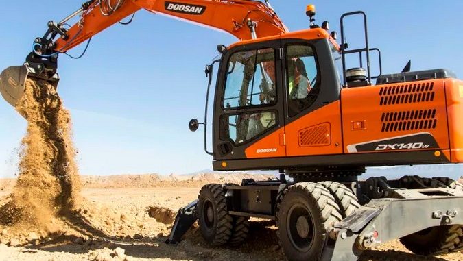
E06524119 means a controller has stopped receiving the AUXIO1 CAN message, which carries vehicle cut-off or safety-bar status. The CE (check engine) lamp comes on as the warning. Per the fault description, the listed causes are electrical or network problems involving the VCU and faults in the CAN wiring harness.
A missing message doesn’t mean the safety-bar switch or the VCU has failed. The fault only tells you the message isn’t arriving, so the job is to find out why. Confirm the code description against the service information for your machine model, serial number, and controller version before you start.
What the Fault Means
Controllers exchange CAN messages at set intervals. Here, the receiving controller expects an AUXIO1 message at each sampling interval and sets the fault when it’s missing for four consecutive receive cycles. That isn’t four seconds. The real time depends on the message’s transmission period.
| Item | Fault information |
|---|---|
| Display code | E06524119 |
| Description | Timeout of CAN receive frame AUXIO1 |
| Related information | Vehicle cut-off / safety-bar status |
| Setting condition | Message missing for four consecutive cycles |
| Warning effect | CE lamp ON |
| Auto-reset condition | Message reception resumes |
Module locations, connectors, and pin assignments vary by application, so work from the wiring diagram for your machine.
Likely Causes
The fault description points to two areas: electrical problems involving the VCU or network, and CAN harness problems involving insulation or resistance. In practice, those break down into the following. The first two rows are general diagnostic practice rather than part of the fault description.
| Area | Typical problems |
|---|---|
| Power and grounds | Blown fuse, unstable supply, loose or corroded ground |
| Connectors | Moisture, damaged terminals, loose locks |
| CAN harness | Open or short circuit, damaged insulation, poor splice |
| Controller | Offline, malfunctioning, or misconfigured |
A controller without power can’t transmit, so start with power and grounds before suspecting a module.
Before You Test
Park and secure the machine per the service procedure, lower the attachments, and prevent any movement. Never bridge or bypass the safety bar or cut-off circuit to silence the warning.
Record the following before changing anything, because clearing codes may erase useful history:
- Machine model, serial number, and controller identification
- The exact code, and whether it’s active or stored
- Any other communication or power faults
- What the machine was doing when the warning appeared
- Recent battery work, electrical repairs, or harness damage
If several controllers report missing messages, look at shared power, grounds, and network wiring first. If the warning is intermittent, note whether it follows vibration, moisture, temperature, or movement of a specific harness section.
Step 1: Live Checks (Power On)
Use the schematic to find the controller that transmits AUXIO1. With the system powered as the procedure specifies:
- Measure supply voltage and ground voltage drop at that controller, under load if the procedure calls for it. A circuit can pass a continuity test and still fail under load.
- Check the ignition-switched feed.
- Watch for the warning changing as you wiggle connectors and harness sections.
Step 2: Power-Off Checks
Switch off and isolate power before disconnecting anything or measuring resistance. Never measure resistance on an energized circuit.
- Inspect fuses, connector locks, seals, and terminals for corrosion, moisture, or damage.
- Trace the CAN branch and look at harness near brackets, sharp edges, moving parts, and earlier repairs.
- Test for opens, shorts between CAN conductors, and shorts to power or ground.
- Check termination using the limits for your network. As a general reference, a typical CAN bus measures roughly 60 Ω between CAN-H and CAN-L with power off, but the correct value depends on the network layout and measurement point, so verify it against Doosan’s documentation.
If everything checks out and the timeout persists, a qualified technician may need a CAN analyzer or oscilloscope to look at network traffic.
Step 3: Safety-Bar Input and Controller
Only once power and communication are confirmed does it make sense to look at the safety-bar input. Compare the physical bar position with the live-data status, and inspect the switch, adjustment, and circuit using the procedure for your application. Consider a controller fault last, after supplies, grounds, wiring, and configuration have been ruled out.
Choosing Diagnostic Equipment
A compatible tool helps you read fault history, watch operating data, and compare conditions before and after the repair. It won’t repair wiring, but it gives you evidence to work from.
Hardware kit and software. If you need both an interface and software, see the Doosan Excavator Diagnostic Tool with DMS-5 options at OBDII Shop. The page offers several software configurations and an optional Lenovo T450 laptop package. The laptop comes only with the matching option, so check what you’re selecting.
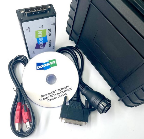
Software only. If you already have compatible communication hardware, see the Doosan / DEVELON DMS-5 Diagnostic Software. The listing describes controller monitoring, sensor-data graphing, saved data, and malfunction-history review on supported applications, with a stated one-time remote installation and activation service. It’s software only, so it doesn’t include an interface.
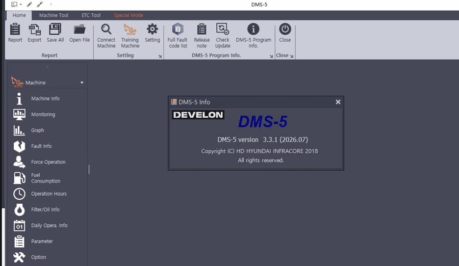
Before you buy, confirm that the setup supports your model and the specific controller reporting the AUXIO1 fault. Neither listing alone guarantees access to this message on every Doosan machine. OBDII Shop can check coverage if you send your machine model, serial number, controller details, and a screenshot of the fault.
Confirming the Repair
The fault resets once the AUXIO1 message is received again, but a stored record may remain, so follow the machine-specific procedure for stored codes. Erasing a code doesn’t restore communication. If the cause is still there, it will return.
- Reconnect and secure everything you inspected.
- Restore power per the procedure and check that the timeout is no longer active.
- Verify safety-bar and cut-off operation with the approved functional test.
- Run the machine through its normal operation and rescan for related communication faults.
A warning that disappears after a restart doesn’t prove an intermittent wiring fault is fixed. Don’t return the machine to service until the safety system is fully restored and tested.
FAQ
Does E06524119 mean the VCU has failed?
Not necessarily. Wiring, connectors, and power faults all produce the same symptom, so test those first.
Where is the safety-bar module?
It depends on the application. Check the service information for your model and serial number.
Can DMS-5 repair a CAN wiring fault?
No. Software can show fault and operating data, but a physical wiring defect needs electrical testing and repair.
Leave a Reply