
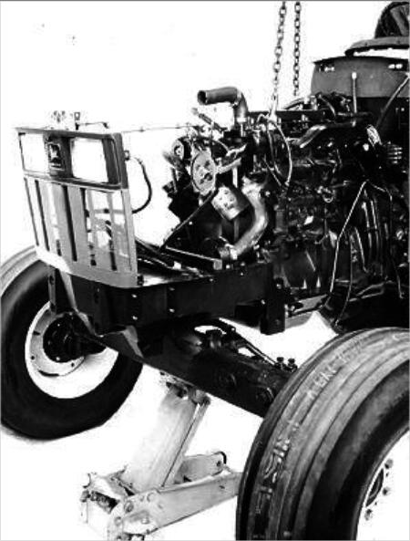
This illustration show you guide on how to remove engine for John Deere 5210/5310/5410 tractor without Cab.
Related Contents:
John Deere Service Advisor 5.3.235 AG+CF 2023 2020 2018 Free Download
John Deere Service Advisor EDL2
John Deere Service Advisor EDL3
Procedures:
1.Remove hood from tractor.
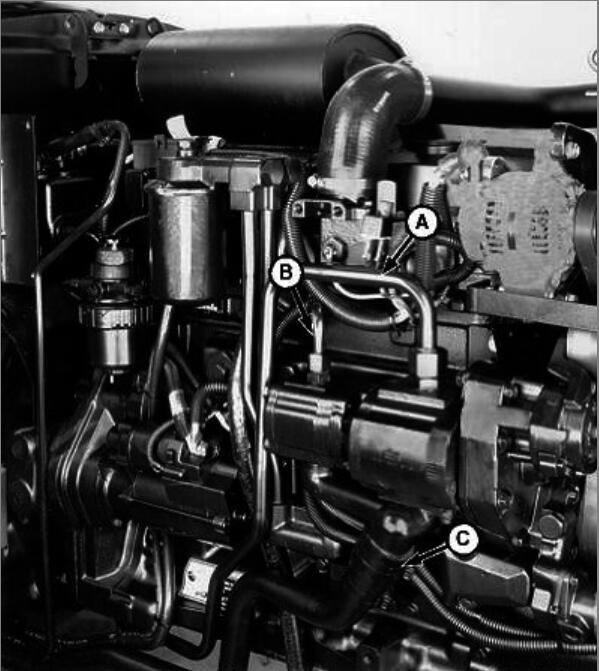
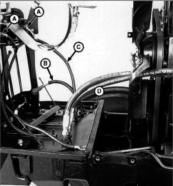
A – Hydraulic Pump-to-Inlet Housing Line
B – Hydraulic Pump-to-Steering Valve Line
C – Suction Line
2.Remove radiator.
3.Remove battery.
4.Remove fuel filter/primer pump.
5.Remove MFWD drive shaft, if equipped.
NOTE:
Close all openings using caps and plugs.
Support suction line (C). Transmission/hydraulic oil will spill out of hose if line drops below transmission/reservoir oil level.
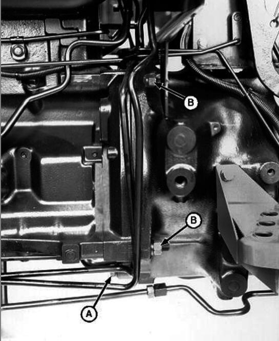
6.Disconnect hydraulic lines (A, B, and C) from pump.
7.Loosen hydraulic lines retaining clamp under right-side floor and step plate and move lines away from engine.
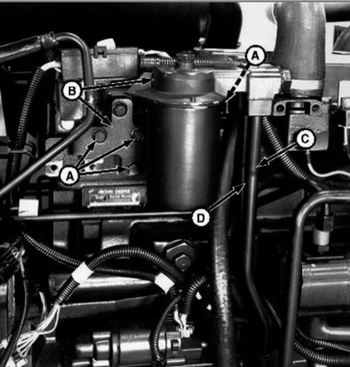
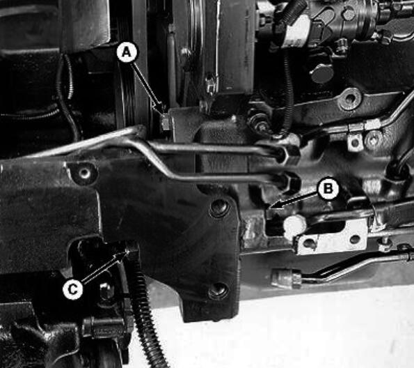
8.LV2332-UN: Cap Screws and Oil Tube
 2)
2)
A – Cap Screw (4 used)
B – Oil Filter and Bracket
C – Oil Tube
D – Oil Tube
9.Remove oil filter and bracket (B).
10.Remove oil tubes (C and D) from engine oil cooler manifold.
11.Cut all tie straps as necessary.
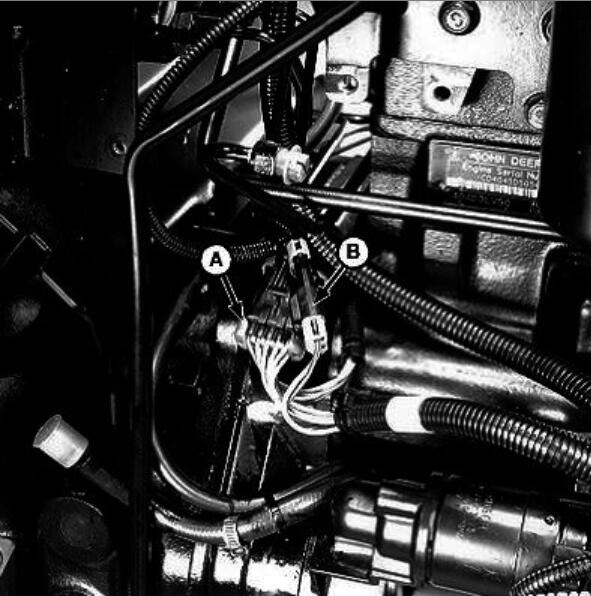
LV2290-UN: Main Harness Wiring Connectors
A – Wiring Connector
B – Wiring Connector
C – Fuel Return Line
D – Right-Side Post (At Fuse Link Junction Block)
LV2291-UN: Fuel Return Line
A – Wiring Connector
B – Wiring Connector
C – Fuel Return Line
D – Right-Side Post (At Fuse Link Junction Block
LV2293-UN: Right-Side Post
A – Wiring Connector
B – Wiring Connector
C – Fuel Return Line
D – Right-Side Post (At Fuse Link Junction Block)
12.Disconnect fuel return hose (C).
13.Disconnect red wire lead #002C from right-side post (D) of fuse link junction block.
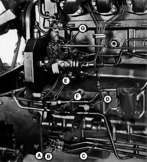
14.Disconnect hydraulic steering lines (A and B).

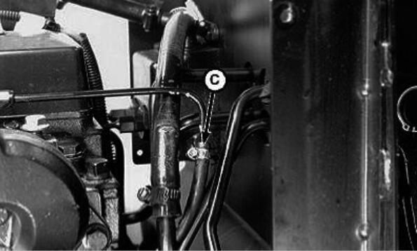
LV2292-UN: Hydraulic Steering Line and Hydraulic Oil Cooler Lines
A – Hydraulic Steering Line
B – Hydraulic Steering Line
C – Clamp
D – Clamp
E – Hydraulic Oil Cooler Line
F – Hydraulic Oil Cooler Line
G – Throttle Control Rod
15.Remove clamps (C and D).
16.Disconnect hydraulic oil cooler lines (E and F).
17.Remove throttle control rod (G).
18.Remove front weights and bracket, if equipped.
CAUTION:
Front weights and bracket must be removed from tractor before removing any frame-to-engine mounting hardware.
LV213-UN: Tractor Without Front Weight Bracket Set
19.Install lifting brackets such as JDG19 or JT01748 Lifting Brackets.
20.Install a support stand under clutch housing.
21.Attach a hoist to engine.
22.Install a floor jack under front axle.
23.Install a wood block between front axle and frame on both sides.
24.Pull battery cable (B) through grommet.
LV2294-UN: Wiring Harness, Headlight Wiring Connectors, and Ground Cable
A – Headlight Wiring Connectors
B – Positive (+) Battery Cable
C – Wiring Harness
D – Ground Cable
25.Disconnect ground cable (D).
26.Disconnect wiring connectors (A) at headlights.
27.Pull wiring harness (C) through grommet.
28.Remove front end support-to-engine cap screws (A and B) and nut (C) from each side of frame.
LV2295-UN: Cap Screws and Nut
A – Cap Screw
B – Cap Screw
C – Nut
29.Roll front end away from tractor.
30.Remove engine-to-clutch housing cap screws (A) and nuts and washers (B).
LV2333-UN: Cap Screws, Nuts, and Washers
A – Cap Screw
B – Nut and Washer
31.Remove engine.
32.Remove clutch.
33.Make repairs as necessary.
More repair case for John Deere,please refer to:John Deere Trouble Repair
Leave a Reply