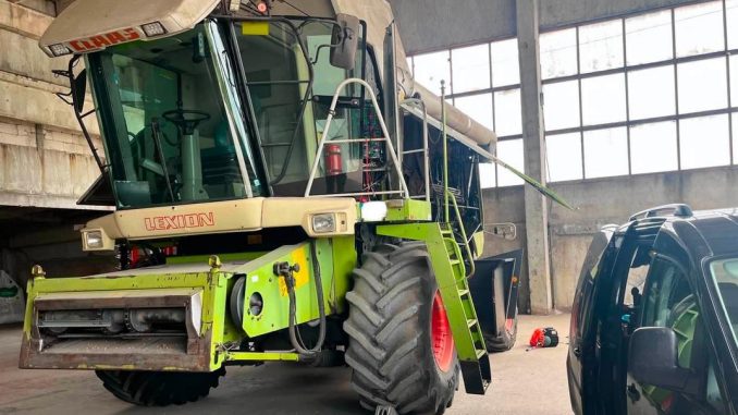
This guide explains how to install the left-hand drum bearing assembly on a CLAAS LEXION 480 combine harvester. Correct installation is essential to maintain proper drum alignment, reduce vibration, and prevent premature bearing or shaft damage.
The procedure includes bearing preparation, taper-lock sleeve installation, hub positioning, pulley installation, and drive-belt adjustment.
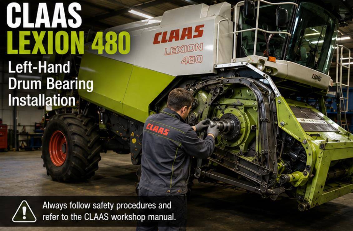
Applicable Machine
- Manufacturer: CLAAS
- Model: LEXION 480
- Repair area: Left-hand drum bearing assembly
Important Safety Information
Before beginning the repair:
- Park the combine on firm, level ground.
- Lower all attachments to a safe position.
- Stop the engine and remove the ignition key.
- Disconnect the battery if required by the service procedure.
- Secure the drum and related components against accidental movement.
- Allow hot components to cool before working nearby.
- Wear suitable gloves and eye protection.
- Use properly rated lifting and supporting equipment.
This procedure should be performed by a trained agricultural equipment technician. Always consult the correct CLAAS workshop manual for the machine serial number before carrying out repairs.
Required Parts and Tools
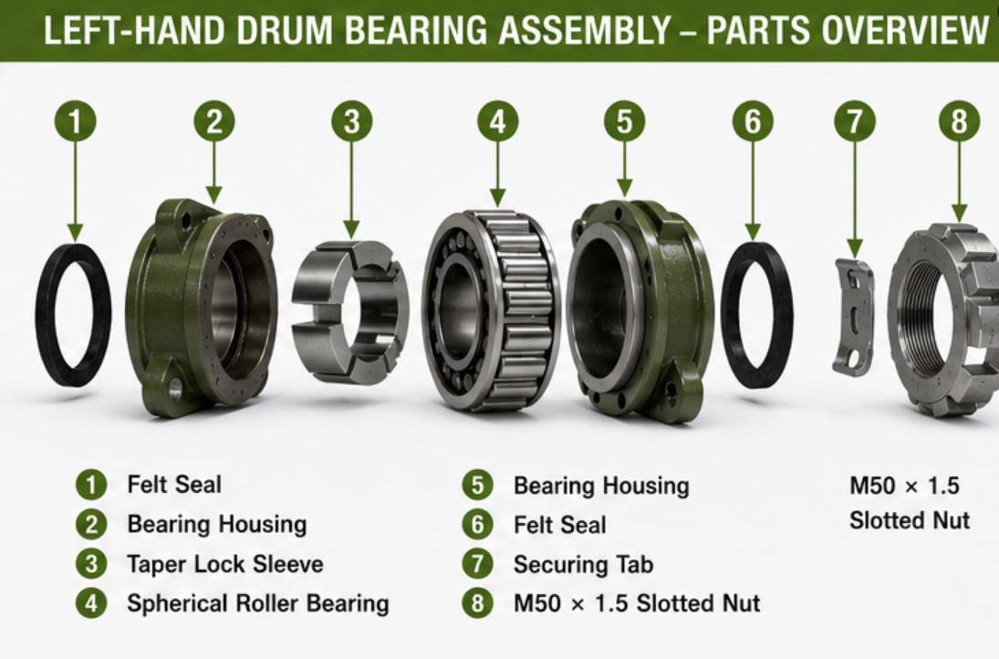
The installation procedure refers to the following components:
- Felt seal
- Bearing housing
- Taper-lock sleeve
- Spherical roller bearing
- Bearing housing
- Felt seal
- Securing tab
- M50 × 1.5 face-end slotted nut
You will also need:
- CLAAS special tool, part number 180 142.0
- Suitable torque wrench
- M12 × 35 cheese-head screw
- M10 × 60 hexagon bolt
- M10 × 25 pulley bolt
- Parallel key
- Grease pipe
- Wooden support wedge, where specified
Tightening Specifications
| Component | Specification |
|---|---|
| M50 × 1.5 slotted nut | 30 Nm, then an additional 68°, followed by alignment with the next securing-tab slot |
| M10 × 60 clamping-hub bolt | 45 Nm |
| M10 × 25 V-belt pulley bolt | 72 Nm |
| Clamping-hub position, dimension X | 61 mm |
Left-Hand Drum Bearing Installation Procedure
1. Clean and Prepare the Bearing Components
Make sure the following parts are completely dry and free from grease:
- Taper-lock sleeve
- Spherical roller bearing
- Shaft bearing seat
Do not apply grease between the bearing bore, taper-lock sleeve, and shaft seat unless specifically directed by the CLAAS service manual. Grease on these surfaces can affect the clamping force and final bearing position.
Inspect the shaft seat for:
- Rust
- Scoring
- Burrs
- Wear
- Surface contamination
Correct any damage before installing the new bearing assembly.
2. Preassemble the Bearing Unit
Preassemble the two bearing housings with the taper-lock sleeve and spherical roller bearing.
The assembly should include:
- Bearing housing
- Taper-lock sleeve
- Spherical roller bearing
- Opposite bearing housing
Position the felt seals on both sides of the bearing assembly.
Carefully slide the complete assembly onto the drum shaft. Avoid striking the bearing directly with a hammer, as impact can damage the rollers, raceways, or seals.
3. Secure the Bearing Assembly to the Drum Wall
Align the bearing housing with the mounting points on the drum wall.
Install the M12 × 35 cheese-head screw and secure the bearing assembly to the drum wall.
Confirm that:
- The bearing housing is seated correctly.
- The felt seals are positioned evenly.
- The bearing is not twisted or forced out of alignment.
- The shaft rotates without binding.
4. Tighten and Lock the Slotted Nut
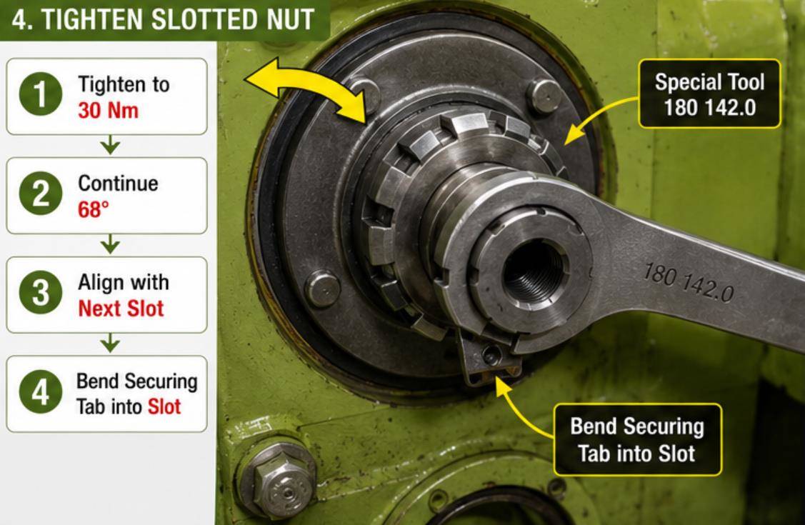
Install the M50 × 1.5 face-end slotted nut.
Using CLAAS special tool 180 142.0, tighten the nut as follows:
- Tighten the nut to 30 Nm.
- Continue tightening the nut by an additional 68 degrees.
- Continue to the next available slot that aligns with the securing tab.
- Bend or tap the securing tab down into the aligned slot.
The securing tab must sit fully inside the nut slot. This prevents the nut from loosening during machine operation.
Do not loosen the nut to align the securing tab. Continue tightening to the next suitable slot as specified in the procedure.
5. Reinstall the Grease Pipe and Cover
Reconnect the bearing grease pipe.
Check that the grease pipe:
- Is not twisted or kinked
- Does not contact moving components
- Is securely attached
- Provides a clear path for lubrication
Remove the temporary wooden wedge used to support or secure the assembly.
Reinstall the assembly cover and confirm that all fasteners are properly secured.
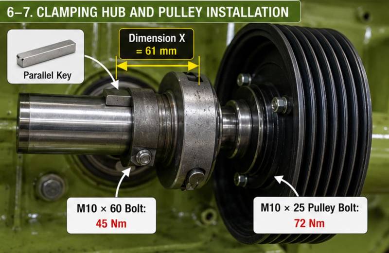
6. Install and Position the Clamping Hub
Place the parallel key into the keyway on the drum shaft.
Make sure the key:
- Fits fully into the shaft slot
- Sits flat
- Is not damaged or distorted
- Does not prevent the hub from sliding into position
Slide the clamping hub onto the shaft.
Measure the hub position according to the applicable CLAAS service illustration. The required dimension is:
Dimension X = 61 mm
Once the hub is correctly positioned, install and tighten the M10 × 60 hexagon bolt.
Tightening torque: 45 Nm
Recheck the 61 mm dimension after tightening. The hub must not move out of position while the bolt is being torqued.
7. Install the V-Belt Pulley
Position the V-belt pulley on the clamping hub.
Install the M10 × 25 bolt and tighten it to:
72 Nm
Make sure the pulley is fully seated and aligned with the other pulleys in the drive system. Incorrect pulley alignment can cause belt tracking problems, excessive belt wear, noise, and vibration.
8. Install and Adjust the Drive Belts
Install the impeller drive V-belt identified as belt K.
Adjust the impeller drive belt according to the relevant CLAAS workshop manual procedure.
Next, install the cutterbar drive belt identified as belt P.
The exact adjustment procedure depends on the cutterbar drive configuration:
- Cutterbar drive without variable-speed drive
- Cutterbar drive with variable-speed drive
Use the appropriate CLAAS service procedure for the machine configuration.
When adjusting the belts, check:
- Belt routing
- Pulley alignment
- Belt tension
- Belt condition
- Clearance from guards and nearby components
Do not overtighten the belts. Excessive belt tension can overload the newly installed bearing and shorten its service life.
9. Reinstall the Guard
After the bearing, hub, pulley, and belts have been installed and checked, reinstall the protective guard.
Confirm that:
- The guard is correctly positioned.
- All guard fasteners are installed.
- The guard does not contact the pulley, belts, or shaft.
- No tools, loose bolts, or cleaning materials remain inside the work area.
Never operate the machine with the drive guard removed.
Final Inspection
Before returning the CLAAS LEXION 480 to service, complete the following checks:
- Confirm all specified fasteners are tightened to the correct torque.
- Verify that the M50 slotted nut is securely locked by the securing tab.
- Recheck the clamping-hub position of 61 mm.
- Confirm the parallel key is correctly installed.
- Check the grease pipe for correct routing.
- Make sure the pulley and belts are aligned.
- Rotate the drum or drive system manually, where safe and permitted.
- Check that the assembly turns smoothly without binding.
- Reinstall all covers and guards.
- Lubricate the bearing according to the CLAAS maintenance schedule.
After starting the machine, operate it initially at low speed and listen for unusual noises. Stop the machine immediately if you notice excessive vibration, abnormal heat, belt tracking problems, or bearing noise.
Common Installation Mistakes to Avoid
Greasing the Tapered Mounting Surfaces
The taper-lock sleeve, bearing bore, and shaft seat must remain dry and free from grease unless the official service documentation states otherwise.
Incorrect Nut-Tightening Sequence
The slotted nut must first be tightened to 30 Nm, followed by an additional 68-degree turn and alignment with the next securing-tab slot.
Incorrect Hub Position
The clamping hub must be positioned at dimension X = 61 mm before the M10 × 60 bolt is tightened.
Excessive Belt Tension
Overtightened drive belts can place unnecessary radial load on the drum bearing and lead to premature failure.
Operating Without the Guard
All protective guards must be reinstalled before the combine is started or returned to service.
Frequently Asked Questions
What bearing is used in the left-hand drum bearing assembly?
The procedure identifies the bearing as a spherical roller bearing installed with a taper-lock sleeve and bearing housings.
Should the taper-lock sleeve be greased before installation?
No. According to the supplied procedure, the taper-lock sleeve, spherical roller bearing mounting surface, and shaft seat must be dry and free from grease.
What is the tightening specification for the M50 slotted nut?
Tighten the M50 × 1.5 slotted nut to 30 Nm, continue tightening by 68 degrees, and then tighten to the next slot that aligns with the securing tab.
What is the correct clamping-hub position?
The specified hub position is dimension X = 61 mm, measured according to the CLAAS service illustration.
What is the tightening torque for the clamping-hub bolt?
The M10 × 60 clamping-hub bolt must be tightened to 45 Nm.
What is the tightening torque for the V-belt pulley bolt?
The M10 × 25 V-belt pulley bolt must be tightened to 72 Nm.
Related CLAAS Diagnostic and Service Resources
For additional CLAAS maintenance, diagnostics, and repair work, technicians may also require:
- CLAAS CDS diagnostic software
- CLAAS CAN diagnostic interface
- 2026.02 CLAAS Part Doc V919 EPC Spare Parts Catalogue
- Model-specific wiring diagrams and workshop manuals
Always verify software, diagnostic interface, and service-document compatibility with the exact CLAAS model, production year, control system, and machine serial number.
More repair case for CLAAS,please refer to CLAAS Trouble Repair
Leave a Reply