
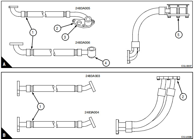
Improved oil cooler pipes have been introduced for the 6-cylinder Phaser 1000 Series engines. The new pipes are separate and do not feature metal braiding. The part number for each pipe is stamped on a clip attached to one end of the pipe (A1 and B1, shown on page 2). There are two pipe arrangements based on application.
Related Contents:
Perkins EST 2024A & 2023A & 2019A Software Free Download
Perkins SPI2 2018A EPC+Service Manual Free Download
Perkins EST Interface EST Diagnostic Adapter 2024A With WIFI
Pipe Arrangements
- Arrangement 1
- No changes to joints.
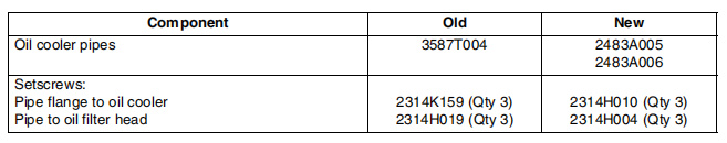
- No changes to joints.
- Arrangement 2
- No changes to setscrews or joints.
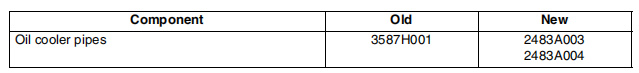
- No changes to setscrews or joints.
Fitting the Pipes (Arrangement 1)
- Position the Setscrews:
- Place the three setscrews in the flange (A2) of the first pipe (part number 2483A005).
- Install a new joint on each setscrew.
- Engage the Setscrews:
- Thread the setscrews into the flange of the oil cooler by three or four threads.
- Insert the spigot (A4) of the second pipe (part number 2483A006) into the hole (A3) of the first pipe’s flange (A2). Ensure it fits squarely.
- Tighten the Setscrews:
- Support the pipes manually and tighten the center setscrew (A5) finger tight.
- Tighten the other setscrews finger tight as well.
- Ensure the pipes are aligned closely together, then tighten the setscrews evenly and gradually to 22 Nm (16 lbf ft or 2.2 kgf m).
- Install the Inner Pipe (Oil Filter Head):
- Place a setscrew in the flange of the inner pipe for the oil filter head.
- Install a new joint on the setscrew, then hold the flange and joint in position while fitting the center setscrew.
- Tighten the setscrews finger tight.
- Position the flange of the outer pipe and insert the third setscrew, tightening it finger tight.
- Starting with the center setscrew, tighten all three setscrews to 22 Nm (16 lbf ft or 2.2 kgf m).
Fitting the Pipes (Arrangement 2)
- Position the Setscrews:
- Place a setscrew in the flange (B2) of the first oil cooler pipe (part number 2483A004).
- Install a new joint on the setscrew and fit the center setscrew.
- Tighten all setscrews finger tight.
- Attach the second pipe (part number 2483A003) to the flange of the oil cooler and insert the third setscrew. Tighten it finger tight.
- Begin tightening with the center setscrew, gradually tightening all three to 22 Nm (16 lbf ft or 2.2 kgf m).
- Install the Inner Pipe (Oil Filter Head):
- Insert a setscrew in the flange of the inner pipe for the oil filter head and install a new joint.
- Hold the flange and joint in place and fit the center setscrew, tightening it finger tight.
- Position the flange of the outer pipe and insert the third setscrew, tightening it finger tight.
- Starting with the center setscrew, tighten all three setscrews to 22 Nm (16 lbf ft or 2.2 kgf m).
Note: The new pipe arrangements are not interchangeable.
More trouble repair case for Perkins,pls refer to:Perkins Trouble Repair
Leave a Reply