Transmission Damage TH48-E80
![]()
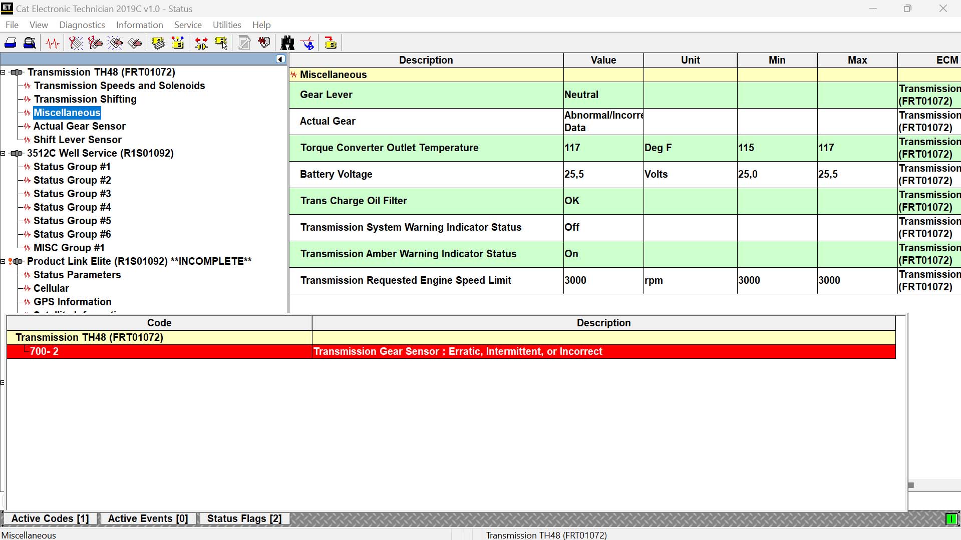
MID 027 CID 0700 FMI 02
Conditions Triggering the Code:
This diagnostic code is logged when the ECM detects irregular data from the transmission position sensor.
Possible Causes:
- Open or short circuit in any of the following wires between the ECM and the transmission position sensor:
- 126-PK (Pink)
- 721-BR (Brown)
- 722-WH (White)
- 723-OR (Orange)
- 724-YL (Yellow)
- 725-GN (Green)
- 726-BU (Blue)
- Open circuit in cable 231-BK (Black) between the transmission position sensor and the frame ground.
- Open circuit in cable J765-BU (Blue) between the transmission position sensor and frame ground.
- Faulty gear position sensor.
- ECM failure.
Verify the position sensor diagnostic code is active before proceeding.
System Response:
The transmission may fail to shift properly.
Test Procedures:
Test Step 1: Check Ground Circuit
- Turn the ignition key and circuit breaker to the OFF position.
- Measure resistance from contact 10 (231-BK/Black) to the frame ground.Expected Result: Resistance should be less than 5 ohms.
Outcome:
- OK: Resistance is less than 5 ohms. Proceed to Test Step 2.
- Not OK: Resistance is greater than 5 ohms, indicating an open circuit in the ground circuit. Repair or replace the wiring harness and recheck for resolution.
Test Step 2: Check Battery Voltage
- Disconnect the engine wiring harness from the switch.
- Turn the ignition key and circuit breaker to the “ON” position.
- At the transmission position sensor harness connector, measure the voltage from the 4-wire connector (126-PK/Pink) to the frame ground.Expected Result: Voltage should approximately match the battery (+) voltage.
Outcome:
- OK: Voltage is correct. Proceed to Test Step 3.
- Not OK: Voltage does not match the battery (+), indicating a defective wiring harness. Repair or replace the wiring harness.
Test Step 3: Check the Wiring Harness
- Use the Electronic Technician (ET) tool to view the transmission position sensor status.
- Replace the Gear Position Sensor with CAT P/N 338-1462 if necessary.
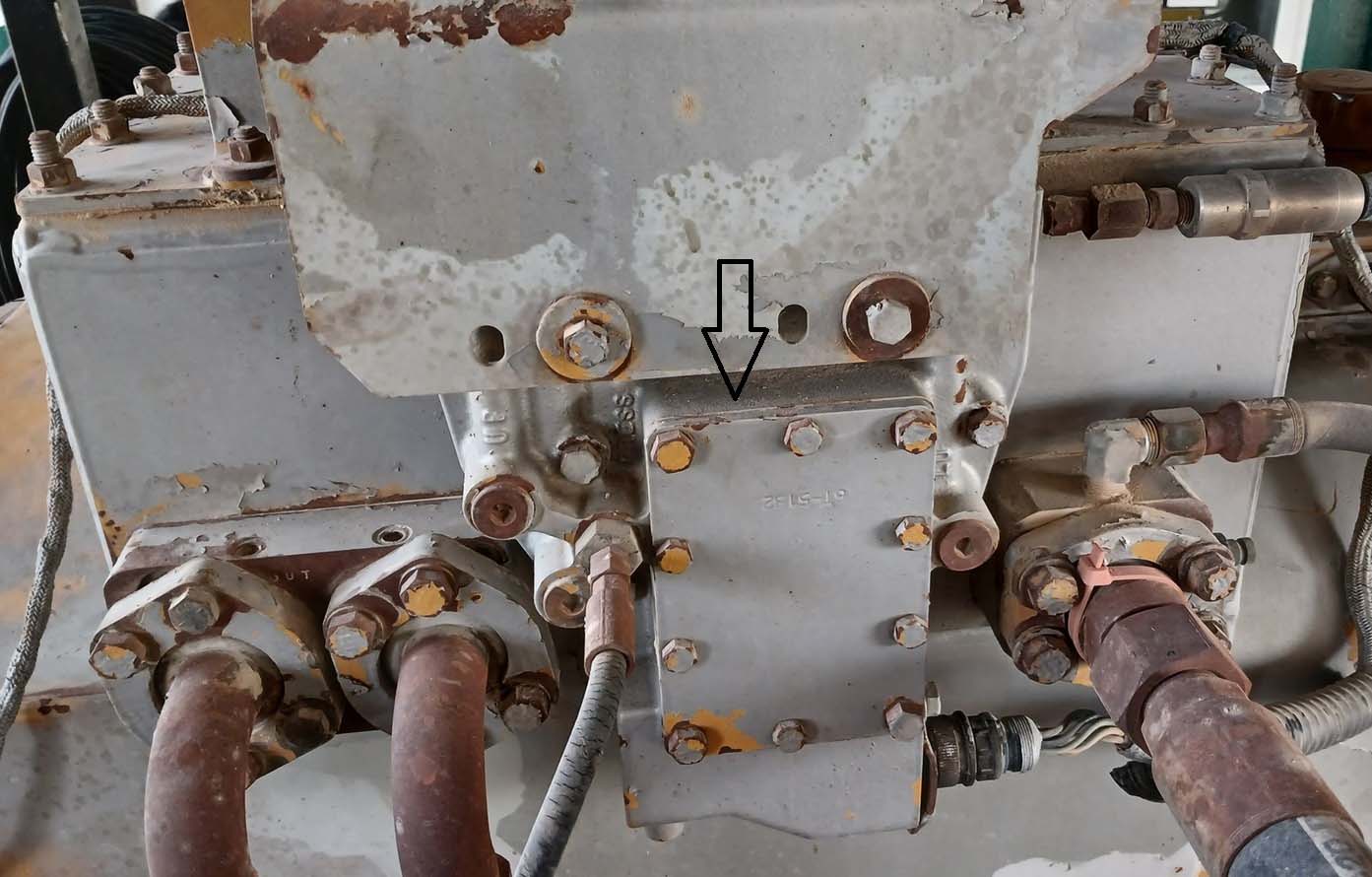
- Procedure for Sensor Replacement:
- Remove the cover, gasket, and bolts on the transmission hydraulic control.
- Disconnect the cable straps.
- Remove the gear position sensor and its connector.
![]()
Note: On the ET status screen, Ground Test (Pin 1) should always indicate grounding. Two other wires will be grounded to reflect the current gear selection, so three wires should be grounded simultaneously, and three wires should remain open.
![]()
![]()
![]()
![]()
Leave a Reply