
This guide details the diagnostic and repair procedures for addressing the SPN 970 – FMI 2 code, which indicates a fault in the Remote Emergency Stop system on a Caterpillar engine.
Code and Description:
- SPN 970 – FMI 2: Remote Emergency Stop Fault, Intermittent, or Malfunctioning
- CDL Code: 337-2
Conditions That Cause This Code:
- The two inputs from the Emergency Stop switch to the ECM are in opposite states.
System Response:
- A diagnostic code is logged when the ECM detects an inconsistency between the signals from the Emergency Stop switch.
How the Emergency Stop Switch Works:
- The ECM monitors two signals from the Emergency Stop switch to determine its status.
- If both signals are open, the ECM shuts off the engine.
- If both signals are connected to the digital return line, the engine continues running.
- If the ECM detects mismatched signals at power-up, it logs a fault but allows the engine to continue running. The engine will stop if both signals are open.
Test Steps for Diagnosis and Repair:
Test Step 1: Check for Active Diagnostic Code
- Turn the main circuit breaker to the “ON” position.
- Start the Caterpillar Electronic Technician (ET) software.
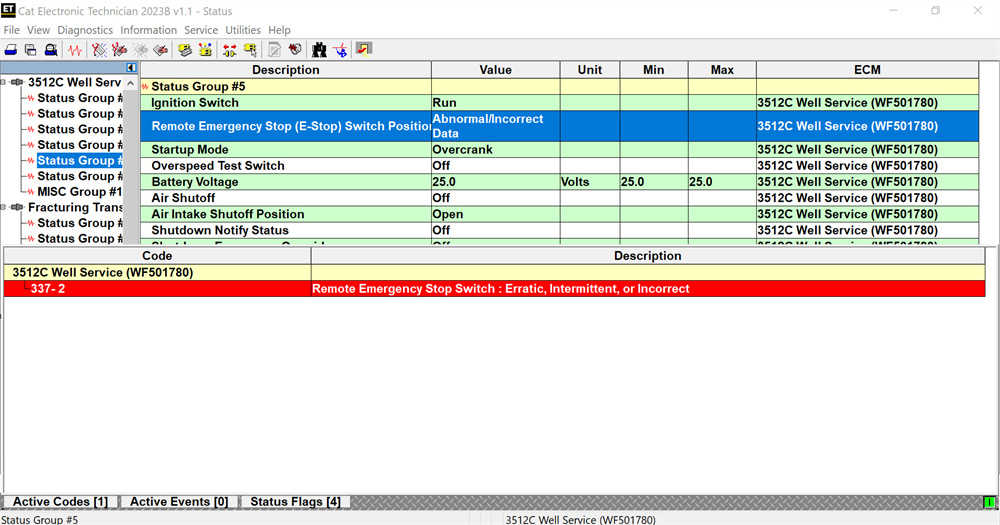
- Check for active diagnostic code 337-2.
- Expected Result: Diagnostic code 337-2 is not active.
- If Not OK: Diagnostic code 337-2 is active.
- Repair: The wires between the ECM and the Emergency Stop switch may be reversed or broken.
- Turn the main circuit breaker to “OFF”.
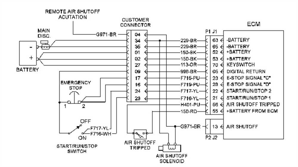
- Remove the J1/P1 ECM connector.
- Measure resistance between P1-23 on the ECM connector and terminal 2 on the Emergency Stop switch.
- Measure resistance between P1-28 on the ECM connector and terminal 2 on the Emergency Stop switch.
- If an open circuit is detected, repair the wires/connectors.
Test Step 2: Check the Condition of the Emergency Stop Switch
- Turn the main circuit breaker to “ON”.
- Start the Cat ET software.
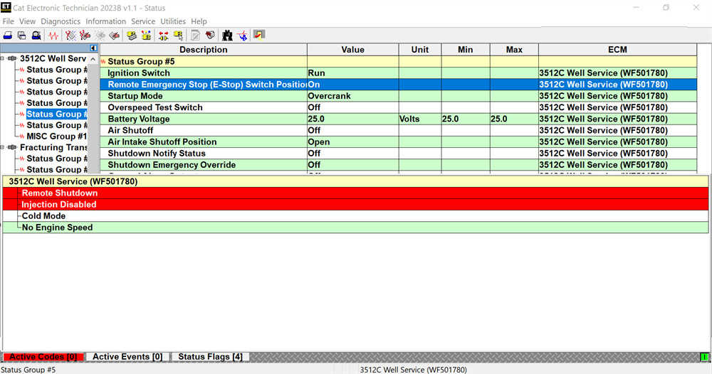
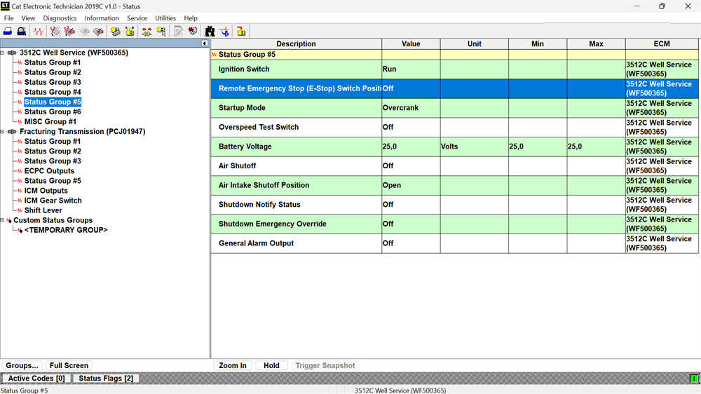
- Observe the Emergency Stop switch status in the Cat ET.
- Activate the Emergency Stop switch (ensure other Emergency Stop switches are not activated).
- Expected Result: Emergency Stop switch status is “ON”.
- If Not OK: Go to Test Step 4.
Test Step 3: Check the Status of the Emergency Stop Switch When Not Actuated
- Disable the Emergency Stop switch (ensure the solenoid valve is retracted and the air shutoff valve is open).
- Observe the Emergency Stop switch status in Cat ET.
- Expected Result: Emergency Stop switch status is “OFF”.
- If Not OK: Go to Test Step 4.
Test Step 4: Test the Operation of the Emergency Stop Switch
- Disconnect the cable from terminal 1 of the Emergency Stop switch.
- Observe the Emergency Stop switch status in Cat ET.
- Install a jumper wire between terminals 1 and 2 on the Emergency Stop switch.
- Observe the Emergency Stop switch status in Cat ET.
- Disconnect power to the ECM and return cables/connectors to their original configuration.
- Expected Result:
- If the cable on terminal 1 is disconnected and no jumper cable is installed, the Emergency Stop switch status is “ON”.
- If the jumper cable is installed, the Emergency Stop switch status is “OFF”.
- If Not OK: The problem is in the wiring between the Emergency Stop switch and the ECM. Go to Test Step 5.
- Expected Result:
Test Step 5: Install a Jumper Cable from the Emergency Stop Switch to the ECM
- Turn the main circuit breaker to “OFF”.
- Remove the J1/P1 ECM connector.
- Disconnect the F715-PU cable from ECM connector P1-23 and install a jumper cable.
- Disconnect the F719-PU cable from ECM connector P1-28 and install a jumper cable.
- Remove wire 998-BR from ECM connector P1-5 and install a jumper cable.
- Reconnect cable 998-BR into the jumper wire plug in socket P1-5.
- Turn the main circuit breaker to “ON”.
- Observe the Cat ET Emergency Stop switch status.
- Connect the jumper cables in sockets P1-23 and P1-28 to the digital return line in socket P1-5.
- Observe the Emergency Stop switch status in Cat ET.
- Turn the main circuit breaker to “OFF” and return cables/connectors to their original configuration.
- Expected Result:
- If the jumper cable is not installed, the Emergency Stop switch status is “ON”.
- If the jumper cable is installed, the Emergency Stop switch status is “OFF”.
- If Not OK: The problem is with the ECM.
Conclusion:
- If the problem is in the ECM or the wiring, replace the ECM or repair the wiring as necessary.
- If the Emergency Stop switch is faulty, replace it and confirm the issue is resolved.
Leave a Reply