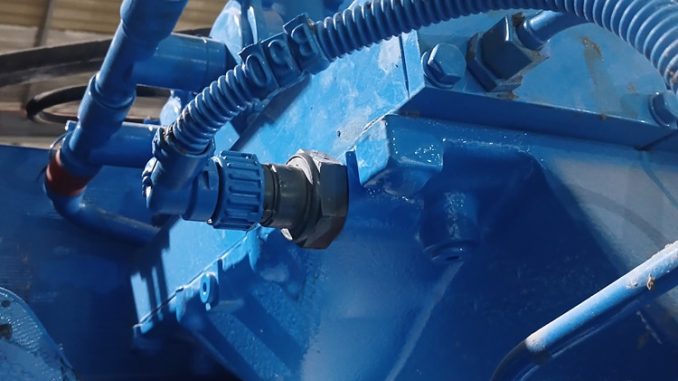
Applicable engine: MTU 12V4000S83L
Alarm number: 214
Diagnostic code: 1.8004.568
Fault description: SD P-CrankCase — crankcase pressure sensor defective, short circuit, or cable breakage
Sensor designation: B50
Replacement sensor part number: 003-535-223
Alarm number: 214
Diagnostic code: 1.8004.568
Fault description: SD P-CrankCase — crankcase pressure sensor defective, short circuit, or cable breakage
Sensor designation: B50
Replacement sensor part number: 003-535-223
MTU fault code 1.8004.568 indicates that the ECU has detected an electrical or internal problem with the crankcase pressure sensor circuit. Possible causes include a defective sensor, an open circuit, damaged wiring, poor terminal contact, or a short circuit.
This guide explains how to retrieve the fault using DiaSys, inspect the B50 crankcase pressure sensor and wiring, replace the sensor when necessary, and clear the error logfile.
Important: Use the correct MTU wiring diagram, connector pinout, and service documentation for the engine serial number before testing or replacing components.
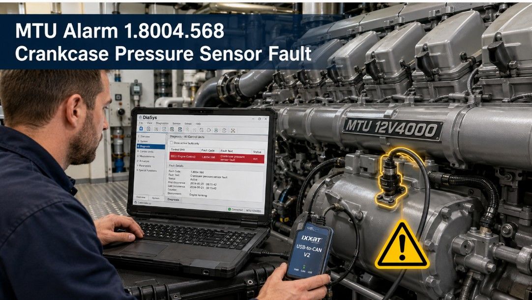
Required Diagnostic Equipment
- Windows laptop with compatible MTU DiaSys software
- IXXAT USB-to-CAN V2 interface
- Compatible diagnostic cable
- Digital multimeter
- Approved electrical test leads or breakout adapters
- Replacement crankcase pressure sensor, if required
- Sensor part number: 003-535-223
Fault Code Summary
| Item | Details |
| Diagnostic code | 1.8004.568 |
| Alarm number | 214 |
| Fault name | SD P-CrankCase |
| Affected component | Crankcase pressure sensor B50 |
| Possible fault type | Sensor defect, short circuit, open circuit, or cable breakage |
| Diagnostic system | MTU DiaSys |
| Control system | ECU-7 ADEC / SAM |
| Replacement sensor | P/N 003-535-223 |
What Does MTU Fault 1.8004.568 Mean?
The ECU monitors the crankcase pressure sensor signal to ensure that it remains within the expected electrical and operating range.
Fault code 1.8004.568 may be stored when the system detects:
- An internally defective crankcase pressure sensor
- A broken or disconnected cable
- An open circuit in the sensor wiring
- A short circuit to power or ground
- Corroded, loose, or damaged terminals
- An implausible sensor voltage
- Poor contact at the B50 sensor connector
The fault should not automatically be treated as proof that the sensor has failed. The power supply, signal circuit, ground circuit, wiring harness, and connector should be checked first.
Safety Precautions
Before beginning diagnosis:
- Stop the engine and secure it against accidental starting.
- Allow hot engine components to cool.
- Follow the vessel, generator, or installation lockout procedure.
- Do not disconnect ECU or sensor connectors with the circuit energized unless the official procedure requires it.
- Use appropriate test leads to avoid spreading or damaging terminals.
- Do not short the 5-volt reference circuit to battery voltage or ground.
- Confirm the correct sensor pinout before taking voltage measurements.
Diagnostic Procedure
1. Connect DiaSys to the SAM Diagnostic Connector
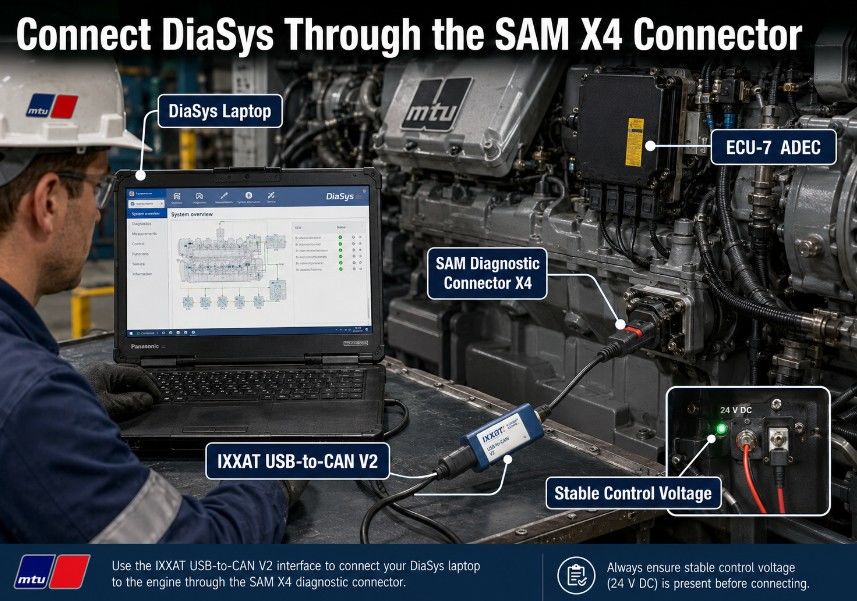
Connect the IXXAT USB-to-CAN V2 interface between the laptop and the SAM diagnostic connector X4.
Start DiaSys and establish communication with the ECU-7 ADEC control system.
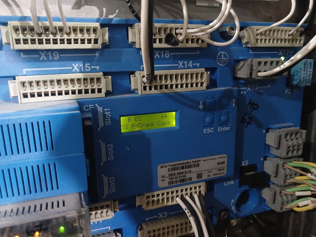
Verify that:
- Windows recognize the interface
- The correct communication driver is selected
- The ignition or control power is switched on
- DiaSys can identify the connected control unit
- Battery or system voltage is stable
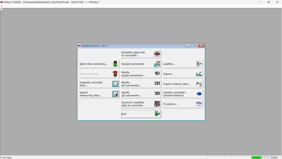
2. Open the Logfiles Menu
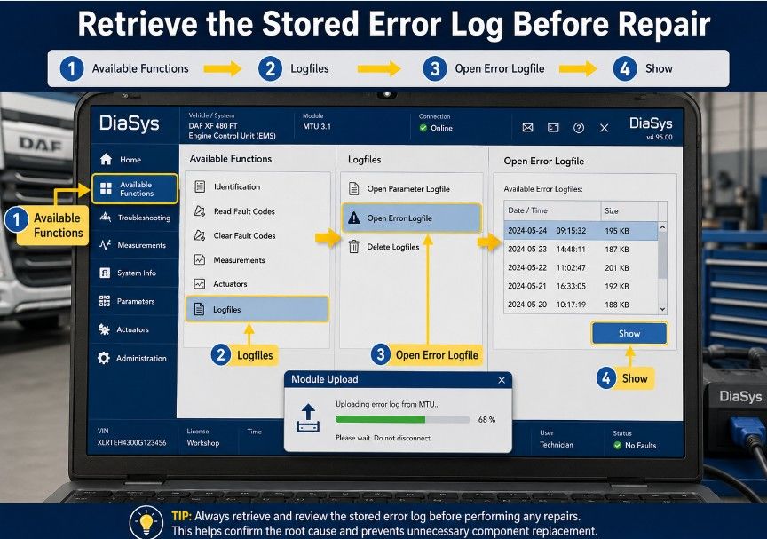
From the Available Functions menu, select:
Logfiles…
This menu provides access to the diagnostic logfiles stored in the governor or control unit.
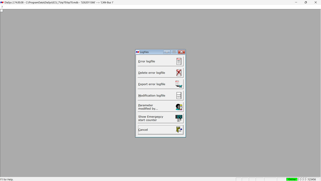
3. Open the Error Logfile
Select:
Open Error Logfile
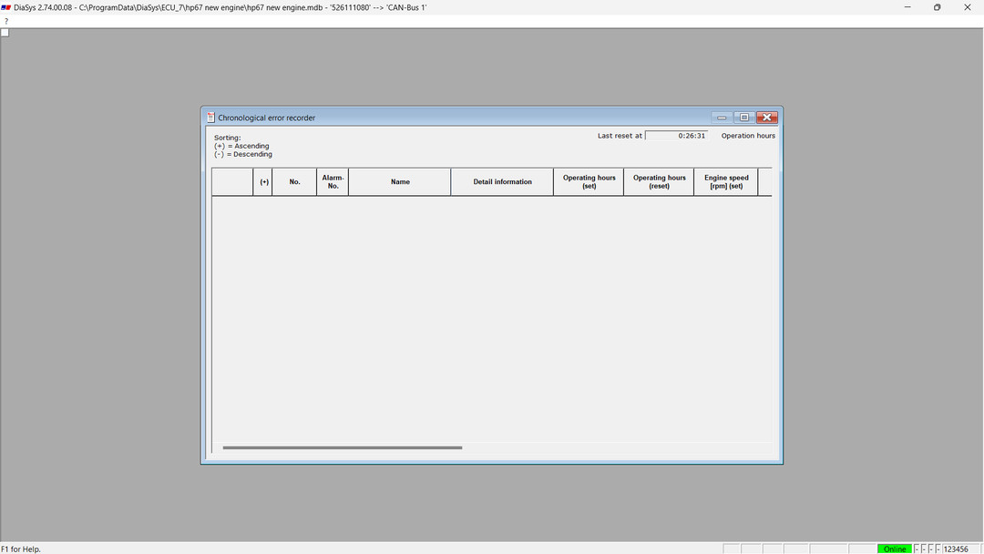
The error logfile displays recorded fault messages in chronological order. It normally contains faults that occurred after the error memory was last deleted.
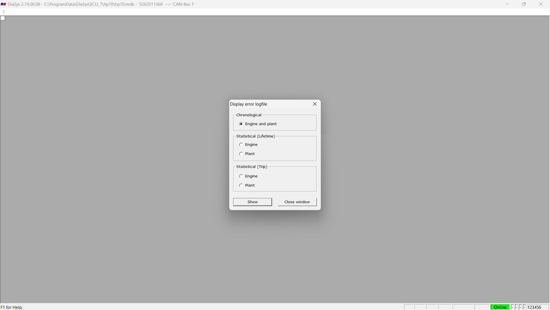
Click:
Show
DiaSys will upload and display the stored error data.
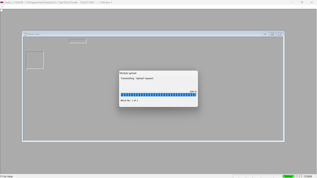
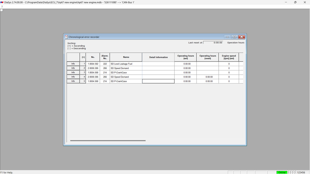
4. Confirm Fault Code 1.8004.568
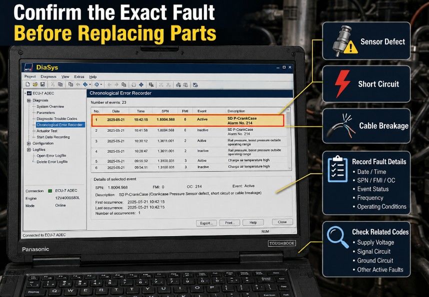
Review the Chronological Error Recorder and locate:
1.8004.568 — SD P-CrankCase
The fault description may indicate:
- Crankcase pressure sensor defective
- Short circuit
- Cable breakage or open circuit
Record the following before clearing the fault:
- Complete diagnostic code
- Alarm number
- Date and time
- Engine operating hours
- Active or inactive status
- Frequency of occurrence
- Related sensor or supply-voltage faults
- Operating conditions when the fault occurred
Check the B50 Sensor and Wiring
5. Perform a Visual Inspection
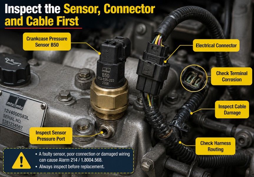
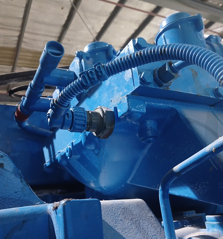
Locate the crankcase pressure sensor B50 and inspect:
- Sensor body for physical damage
- Connector for moisture or contamination
- Terminals for corrosion or looseness
- Harness for cuts, abrasion, or heat damage
- Cable routing near sharp edges or moving components
- Wiring for oil contamination
- Connector seals and locking tabs
- Harness strain near the sensor
Repair damaged wiring or connector terminals before replacing the sensor.
6. Check the Sensor Voltage
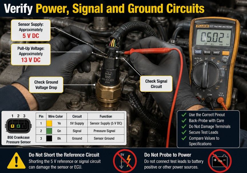
Using the correct MTU wiring diagram and approved test procedure, measure the electrical supply at the B50 connector.
The values provided for this procedure are:
- Sensor supply voltage: approximately 5 V DC — OK
- Pull-up voltage: approximately 13 V DC — OK
Do not rely on voltage alone. A circuit may show the correct voltage without carrying current correctly. Where permitted by the service procedure, also check:
- Ground-circuit voltage drop
- Circuit continuity
- Short to ground
- Short to supply voltage
- Terminal tension
- Signal response
- Intermittent faults while gently moving the harness
Disconnect the ECU and sensor before performing resistance or continuity tests unless the official MTU procedure states otherwise.
How to Interpret the Test Results
| Test result | Recommended action |
| 5 V supply missing | Check ECU supply circuit, open wiring, short circuit, and connector terminals |
| Pull-up voltage incorrect | Inspect the signal circuit, ECU connection, and harness |
| Ground circuit has excessive voltage drop | Repair the ground circuit or poor terminal connection |
| Wiring open or shorted | Repair or replace the affected wiring |
| Connector damaged or corroded | Repair the terminals or replace the connector |
| Wiring and voltages correct, but fault remains | Replace the B50 crankcase pressure sensor |
| Fault returns after sensor replacement | Recheck wiring, pin fit, ECU input circuit, and installation-specific documentation |
Replace the Crankcase Pressure Sensor
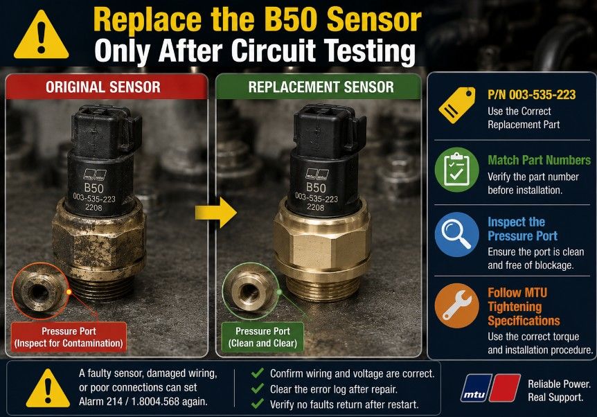
If the wiring, connector, reference voltage, signal circuit, and ground are within specification but the fault remains, replace sensor B50.
Replacement part number:
003-535-223
Follow the official MTU removal and installation procedure, including any specified tightening torque, sealing requirements, and calibration instructions.
Before installing the new sensor:
- Compare the old and new part numbers.
- Inspect the connector and harness again.
- Confirm that the pressure port is not blocked.
- Check for oil sludge, contamination, or damaged sealing surfaces.
- Do not apply sealant unless specified by MTU.
- Tighten the sensor to the approved torque.
Clear the Error Logfile
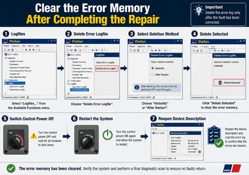
After completing the repair, return to the DiaSys Logfiles menu and select:
Delete Error Logfile
This function deletes stored error messages from the governor.
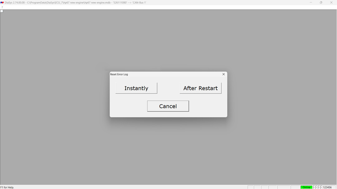
Choose the appropriate deletion method:
- Instantly
- After Restart
Then click:
Delete Selected
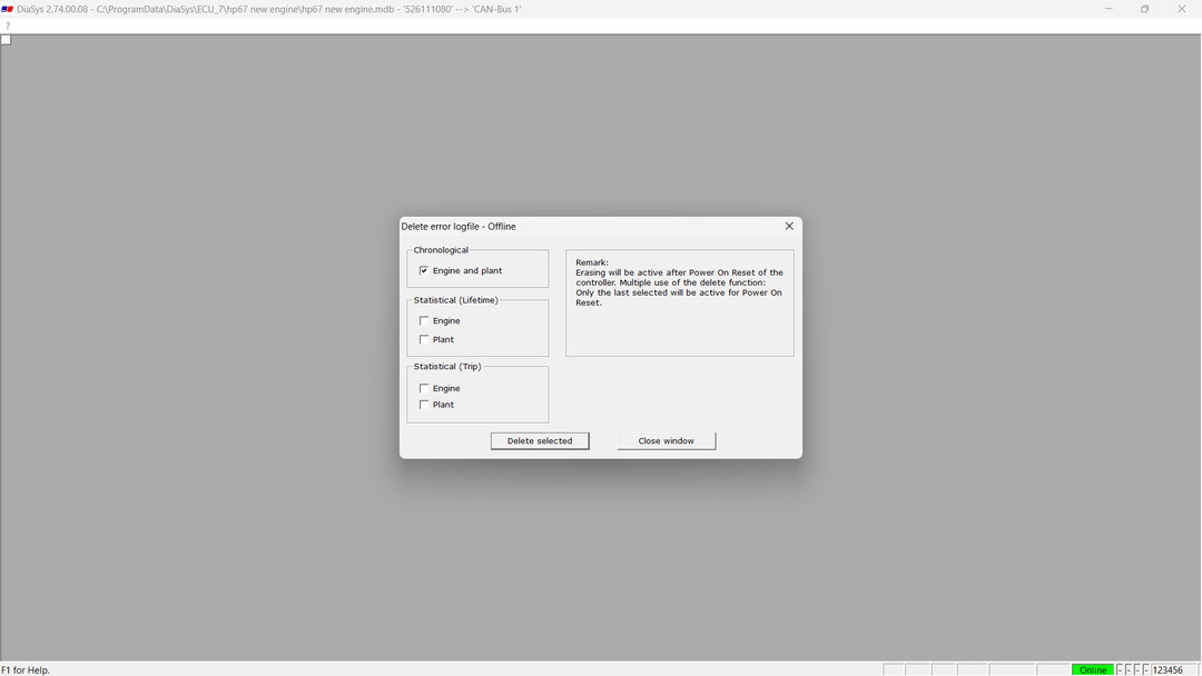
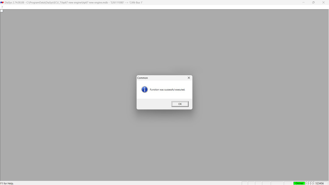
After the function has completed:
- Switch the device or control power off.
- Wait for the system to shut down completely.
- Switch the device on again.
- Reopen the device description in DiaSys.
- Reconnect to the ECU.
- Read the error logfile again.
Final Verification
Do not return the engine to service immediately after deleting the fault. Confirm that the repair has corrected the underlying problem.
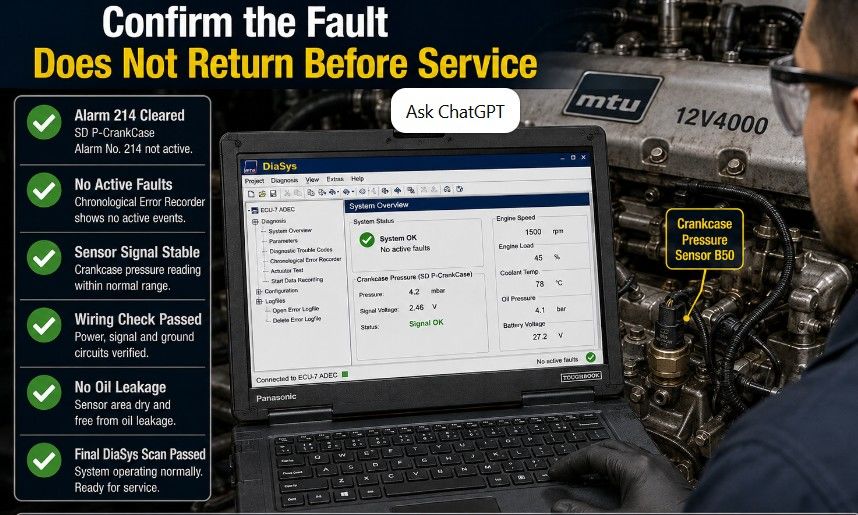
Complete the following checks:
- Start the engine according to the approved procedure.
- Confirm that Alarm 214 does not return.
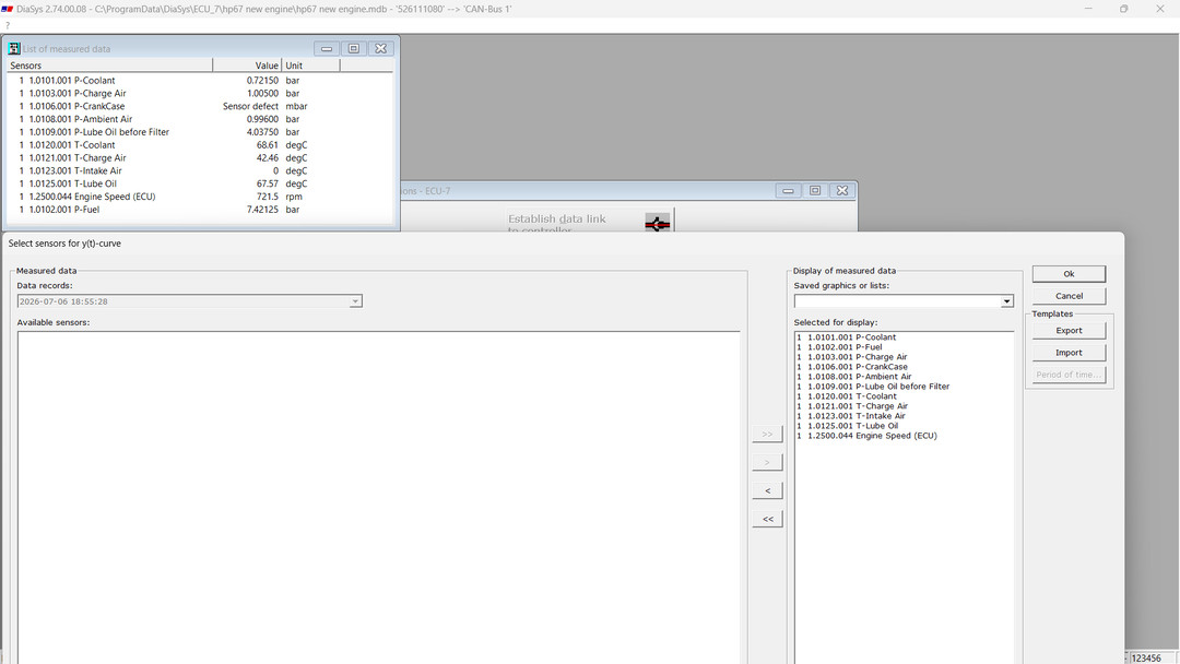
- Monitor the crankcase pressure value in DiaSys.
- Check that the reading is stable and plausible.
- Gently move the wiring harness to check for intermittent faults.
- Inspect the replacement sensor for leakage.
- Confirm that no related supply-voltage or sensor faults are active.
- Allow the engine to reach normal operating temperature.
- Perform a final diagnostic scan.
- Save the final logfile for the maintenance record.
Common Diagnostic Mistakes
Replacing the sensor without checking the wiring
A broken conductor, loose terminal, or short circuit can produce the same fault as a defective sensor.
Measuring voltage with the wrong pinout
Testing the wrong terminal can damage the sensor or ECU. Always confirm the connector identification and PINs.
Clearing the logfile before recording the fault
Save the code, timestamp, occurrence count, and related operating data before deleting the error memory.
Ignoring intermittent harness damage
A cable may test correctly while stationary but fail when exposed to engine vibration or movement.
Assuming correct supply voltage proves the circuit is good
A high-resistance terminal may show the correct unloaded voltage. Voltage-drop and terminal-contact checks may still be required.
Frequently Asked Questions
What does MTU code 1.8004.568 mean?
It indicates an electrical or internal fault involving the B50 crankcase pressure sensor. The possible causes include sensor failure, a short circuit, an open circuit, or cable damage.
What is Alarm No. 214 on an MTU 12V4000S83L?
In this procedure, Alarm 214 corresponds to SD P-CrankCase, indicating a crankcase pressure sensor or circuit fault.
Which diagnostic software is used?
The procedure uses MTU DiaSys with an IXXAT USB-to-CAN V2 interface connected through the SAM X4 diagnostic connector.
What voltage should be present at the sensor?
The supplied procedure references approximately 5 V DC sensor voltage and approximately 13 V DC pull-up voltage. Confirm these values and the test points against the wiring diagram for the specific engine installation.
What is the B50 sensor part number?
The specified replacement crankcase pressure sensor is P/N 003-535-223.
Should the fault code be cleared before replacing the sensor?
Record the complete logfile first. Clear the fault only after the wiring, connector, and sensor have been inspected or repaired.
What should be done after deleting the error logfile?
Switch the control system off and on again, reopen the device description in DiaSys, reconnect to the ECU, and confirm that the fault does not return.
Conclusion
MTU fault code 1.8004.568 / Alarm 214 points to a problem with the B50 crankcase pressure sensor or its electrical circuit. A reliable diagnosis requires more than replacing the sensor: technicians should first retrieve and save the DiaSys logfile, inspect the connector and harness, verify the 5-volt supply and pull-up circuit, and check for open circuits, shorts, or poor terminal contact.
When the wiring and voltage tests are satisfactory, but the fault remains, replace the crankcase pressure sensor with P/N 003-535-223, clear the error logfile, restart the control system, and perform a final operational scan.
More Diesel Engine Resources
For additional fault-code solutions, diagnostic procedures, and software instructions, explore our
diesel engine diagnostic and repair guides
Leave a Reply