
The Electrical system function in Scania SDP3 allows you to troubleshoot vehicle electrical systems effectively. SDP3 communicates with all vehicle control units simultaneously, giving you access to fault codes, signals, activations, adjustments, calibrations, and detailed system descriptions.
Related product
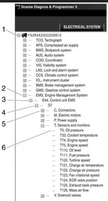
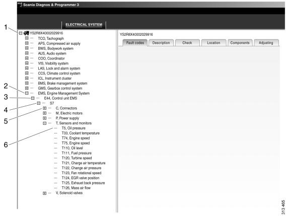
Navigation Structure
The navigation in SDP3 mirrors the vehicle’s electrical system:
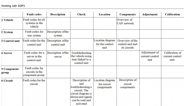
- Vehicle – Overview of the vehicle’s electronic control systems.
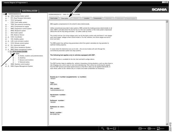
- ECU System – Each control unit with its related circuits and components.
- Control Unit – Hardware details of the unit.
- Server – Software-related details and available functions (checks, adjustments, calibrations).
- Component Group – Circuits grouped by their main component.
- Circuit – Detailed circuit-level information for troubleshooting.
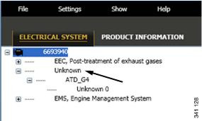
Note: Unsupported control units appear as “Unknown” in the tree structure.
Fault Codes
- View and clear fault codes at vehicle, system, or control unit level.
- Active fault codes = currently present issues.
- Inactive fault codes = previously registered, but no longer active.
- Primary codes = original faults. Secondary codes = faults triggered due to a primary fault elsewhere.
- Fault codes are timestamped (local time by default, with UTC as an option).
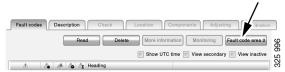
- Marine/industrial engines may include “Fault Code Area 2” (all-time history, non-deletable).
Indicators:
- Exclamation mark (!) shows active fault codes across all levels of the navigation tree.
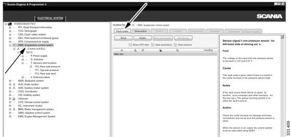
Background Information:
- For some codes, saved diagnostic values are available. These may not always align with the exact time the fault was generated, since tests run before the fault is confirmed.
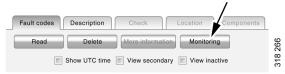
Fault Code Monitoring:
- Useful to verify whether a fault has been fully resolved.
- Allows continuous status read-out of monitored fault codes.
- Essential when faults require multiple drive cycles or long validation before clearing.
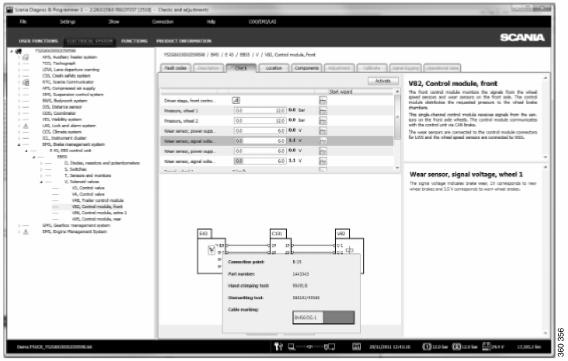
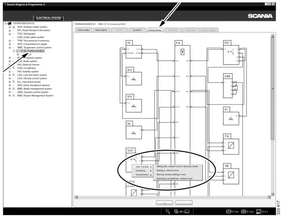
Circuit Checks
- Circuit diagrams are displayed for selected circuits.
- You can read signals, activate components, and test functionality.
- Hovering the cursor provides extra data:
- Over a harness = cable markings.
- Over a pin = terminal part number, crimping/dismantling tool, and marking.
- Right-clicking components links directly to related user functions.
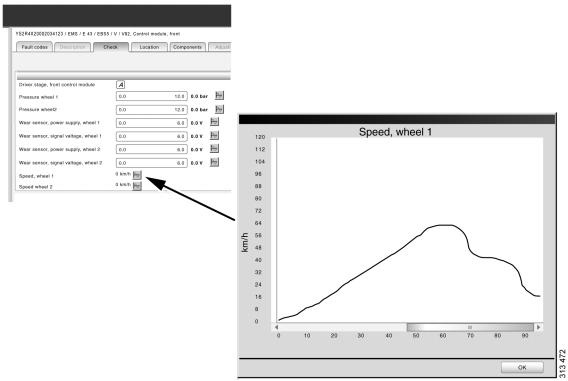
- Values can be plotted in diagrams for easier analysis.
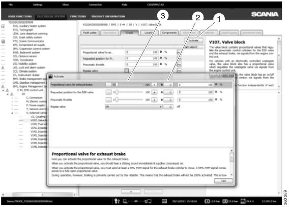
Activation
- SDP3 can control ECU inputs/outputs temporarily for testing.
- Modes include:
- Toggle activation (press once to activate/deactivate).
- Timed activation (auto stop after set time).
- Spring-loaded (hold button for activation).
- Safety: Press spacebar anytime to stop activation.
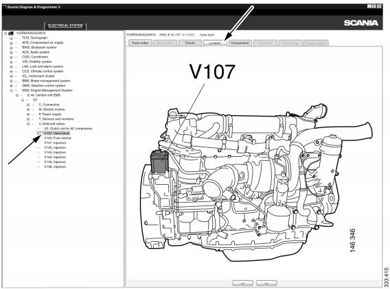
Location Diagrams
- Show physical locations of components in the vehicle.
- Multiple diagrams may exist; use arrows to navigate.
- Double-click to open diagrams in new windows for multitasking.
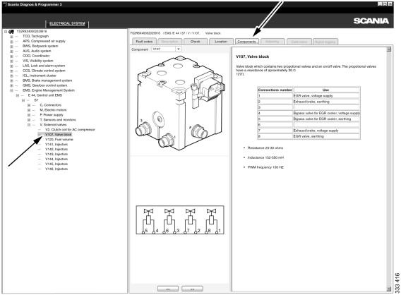
Components
- Lists detailed descriptions of components in a circuit.
- Navigation tree highlights where each component connects.
- Right-clicking allows quick access to related functions or checks.
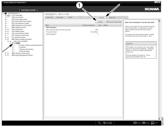
Adjustments
- View and change customer parameters stored in control units.
- Parameters saved to the SOPS file for reuse after part replacement.
- Symbols:
- Red dot = value changed.
- Green tick = adjustment successful.
- Factory flake icon = original factory value.
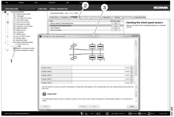
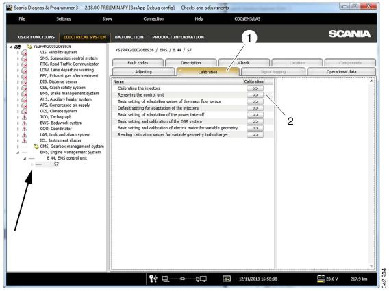
Calibration
- Reset and calibrate ECU values.
- Guided wizard assists with calibration steps.
- Settings are not stored for reuse during part replacement.
Signal Logging
- Record and save ECU signals for troubleshooting.
- Workflow:
- Select server → signals → mark signals to log.
- Start/stop/save recordings.
- Use timestamps to flag key moments.
- Saved signal lists can be reused or shared with Scania Helpdesk for analysis.
Summary:
Using Scania VCI 3 with SDP3 under Electrical system gives full visibility into fault codes, circuits, activations, calibrations, and signal logging. This structured approach helps technicians efficiently diagnose and resolve electrical issues in Scania vehicles.
Leave a Reply