
Here is an instruction show you guide on how to remove and calibrate primary hydraulic power system electro-hydraulic remote valve for New Holland T6030 tractor.
Related Contents:
New Holland Electronic Service Tools (CNH EST 9.7 9.6 8.6 engineering Level) CNH Kit Diagnostic Tool
New Holland Electronic Service Tools(CNH EST 9.7 9.6)Engineering Level Diagnostic Software
New Holland Electronic Service Tools CNH kit diagnostic tool (CNH EST 9.7 9.6 8.6 engineering Level ) Plus lenovo X230 laptop
2022 New Holland Electronic Service Tools 9.7 9.2 CNH EST Software Free Download
Procedures:
Removal:
1 Steam clean remote control valve assembly prior to removal.
Lower hydraulic links.
Remove covers on remote valve couplers.
Remove support for pneumatic trailer brake couplers (where fitted).
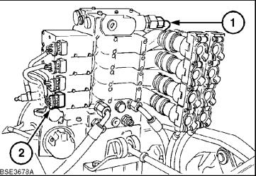
2 Disconnect harness from electronic draft control solenoids, remote valve solenoids (2) and pressure feed hose (1).
NOTE: Identify the remote valve connectors to facilitate correct re-installation
3Disconnect the lift cylinder hydraulic hoses from the EDC slice (1)

4Using suitable lifting equipment support remote valve assembly, remove the three base securing bolts and lift valve stack from tractor
Calibration:
NOTE: The calibration procedure is controlled by the electronic management system. To prevent inadvertent movement of the tractor, park the tractor away from any obstacles, firmly apply the parking brake and block the wheels,
front and rear. Check that the Ground speed display is Zero before commencing.
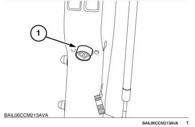
1 Install the diagnostic connector 380000843 into the diagnostic socket (1)
2 Disconnect all implements from the rear remotes.
3 Make sure all EHR program switches are in the OFF position.
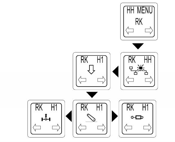
4 Use the “h”, “m” and “dimming” keys on the instrument cluster to navigate the HH menu’s to H1 and the rear EHR symbol on the RK controller.
The lower central display will show “CAL”
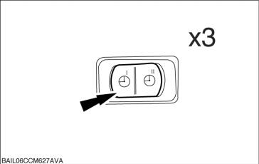
5 Depress the program switch for lever No.1 three times.
BAIL06CCM627AVA 3
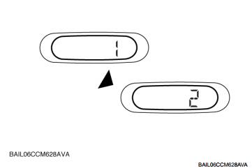
6The calibration will proceed, the program lamp for EHR 1 will be illuminated and the lower central display will show “1”.
When the neutral position has been acquired and stored, the program lamp is turned off and the lower central display will show “2”
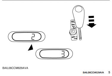
7 While 2 is displayed move the lever to the raise position, the program light will illuminate.
When movement is detected the program lamp for
EHR 1 is turned off. After the raise position is established the lower central display will change to 3, the program light will switch off
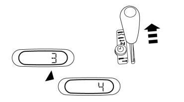
8 While 3 is displayed move the lever to the full flow lower position, the program light will illuminate.
When a stable value for the full flow lower position of the lever is seen it is recorded with the minimum flow rate value, the lower central display will change to 4, the program light will switch off
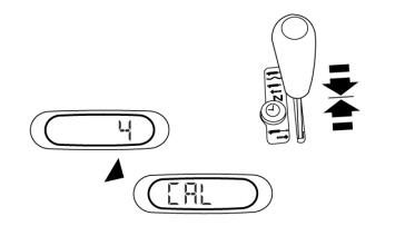
9While 4 is displayed move the lever to the float position, the program light will illuminate.
When a stable value for the float position of the lever is seen and recorded the lower central display will change to “CAL” to indicate the calibration procedure is complete
10To calibrate the remaining EHR levers (2 to 4), repeat the steps 5 to 9.
11Key OFF to store the calibration values.
NOTE: If a lever is not calibrated the program lamp is switched on regardless of the program switch state
More topics for New Holland repair,pls refer to:New Holland Trouble Repair
Leave a Reply