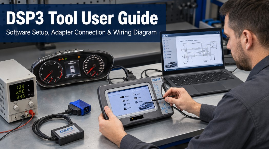
The DSP3 tool uses dedicated PC software and vehicle-specific adapters to provide access to supported instrument-cluster and odometer-related service information.
One of the most useful functions for technicians is the built-in vehicle selection and wiring diagram reference. After selecting the appropriate vehicle application, DSP3 can display the connection information needed for the supported module.
This guide explains the basic DSP3 workflow, from opening the software to locating the correct wiring diagram.
Important: Odometer-related functions should only be used for legitimate instrument-cluster repair, module replacement, data restoration, or other work permitted by applicable laws. Always record the original vehicle mileage and follow local disclosure requirements.
Before Using DSP3
Before starting, prepare:
DSP3 main unit/pad
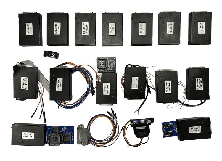
Compatible DSP3 adapter
Windows computer with DSP3 software installed
Stable USB or communication connection
Vehicle or instrument cluster being serviced
Stable power supply when required
Before connecting to an electronic module, confirm that the selected adapter and wiring diagram match the exact vehicle and instrument-cluster application.
Do not connect wires based on connector appearance alone.
Recommended DSP3 Tool
If you need the DSP3 hardware used in this guide, the Original DSP3+ Odometer Correction Tool Limited Edition provides the DSP3 platform together with a selected set of commonly used adapters for supported automotive module service.
According to the current product information, the Limited Edition uses the same core software and functions as the Full Package but removes some less commonly used accessories. It supports supported odometer-related applications as well as selected airbag, radio, immobilizer, EEPROM, and MCU programming functions. Vehicle and module coverage should always be checked before ordering.
Compatibility Tip: Confirm the exact vehicle, instrument cluster, EEPROM/MCU type, required adapter, and supported function before purchase.
Step 1: Open the DSP3 Software
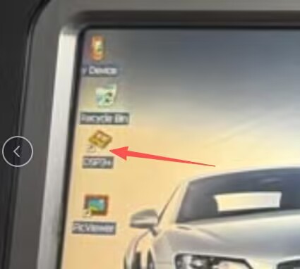
Locate the DSP3 program on the computer and double-click the application icon.
Allow the program to finish loading before connecting or selecting a vehicle application.
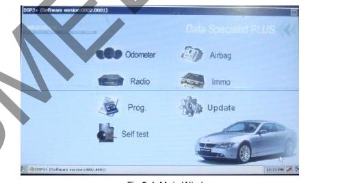
Step 2: Confirm the DSP3 Main Interface
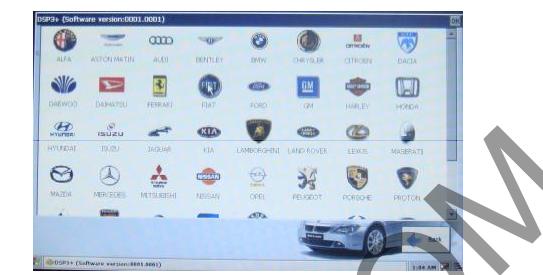
After the program starts, the DSP3 main screen should appear.
Before continuing, check that:
The software opens normally.
No communication error is displayed.
The DSP3 device is available.
The required adapter is ready.
If the software does not open correctly, resolve the software or driver problem before working on the vehicle module.
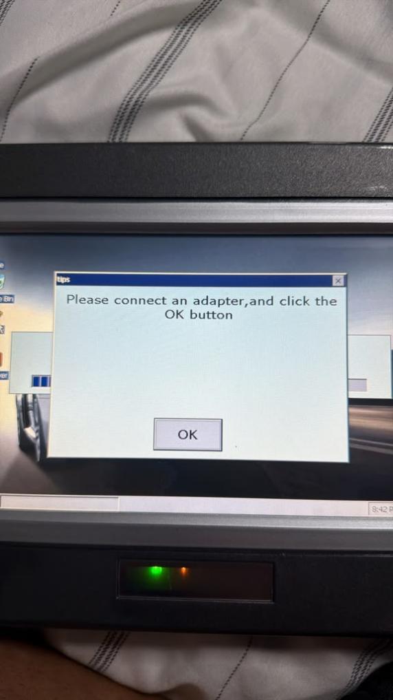
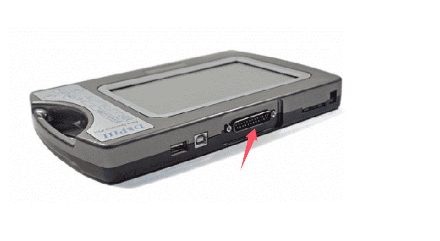
Step 3: Connect the Correct Adapter to the DSP3 Pad
Connect the required adapter to the DSP3 pad/main unit.
Before Making the Connection
Verify:
Adapter type matches the selected application.
Connector orientation is correct.
Pins are not bent or damaged.
Cables are fully inserted.
No exposed terminals can short together.
Do not force a connector into the DSP3 unit or vehicle module.
Step 4: Open the Odometer Menu
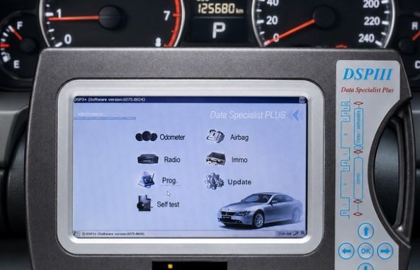
From the DSP3 software interface, enter the appropriate function menu and select:
Odometer
The exact vehicle-selection structure may depend on the DSP3 software version and supported application.
Choose the vehicle and module that match the unit being serviced.
Step 5: Select the Vehicle Application
After entering the Odometer section, navigate to the required vehicle application.
The software should then display the corresponding service page.
Carefully confirm:
Vehicle manufacturer
Model
Applicable model year or generation, when shown
Instrument-cluster type
Adapter required
Connection points
Selecting an incorrect application can result in incorrect wiring instructions.
Step 6: View the Wiring Diagram
Once you select the correct vehicle or module, DSP3 can display the corresponding wiring diagram.
Use the diagram to identify the required connections before beginning module service.
Pay attention to labels such as:
Power
Ground
Data
Clock
CAN High
CAN Low
EEPROM/MCU connection points
Adapter pin assignments
Use only the connections shown for the selected DSP3 application.
Tip: Save a screenshot of the wiring diagram before starting. This provides a convenient reference while connecting the adapter and can help document the original setup.
Recommended DSP3 Workflow
For a safer and more repeatable process, use this sequence:
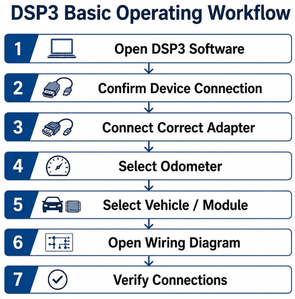
Open DSP3 → Confirm Device Connection → Connect Correct Adapter → Select Odometer → Select Exact Vehicle/Module → Open Wiring Diagram → Verify Connections → Begin Authorized Service
Do not skip the wiring verification step.
If the DSP3 Wiring Diagram Does Not Appear
If the selected application does not display the expected wiring information, check the following.
Confirm the Vehicle Selection
Make sure you selected the correct:
Manufacturer
Vehicle model
Generation
Cluster/module type
A similar model may use different electronics.
Check the DSP3 Software
If the required application is missing, the installed software database may not contain that vehicle or module.
Do not substitute a diagram from another model unless you confirm the hardware and pinout are identical.
Check Device Communication
If DSP3 does not communicate normally:
Reconnect the DSP3 device.
Check the USB connection.
Try a direct computer USB port.
Confirm required drivers are installed.
Restart DSP3 software
Inspect the Adapter
Check for:
Damaged pins
Broken cables
Loose connectors
Incorrect adapter selection
Poor electrical contact
Common DSP3 Operating Mistakes
Selecting the Wrong Vehicle
Models that look similar may use different instrument clusters, EEPROMs, MCUs, or connector pinouts.
Always select the exact supported application.
Connecting the Adapter Before Checking the Diagram
Review the wiring information first whenever the procedure requires direct module connections.
Incorrect wiring may damage the module or diagnostic equipment.
Forcing a Connector
If an adapter does not fit correctly, stop and verify the adapter number and connector orientation.
Ignoring Original Vehicle Data
For legitimate cluster replacement or repair, document the original mileage and relevant module information before changing or restoring data.
Using an Unstable Computer Connection
A loose USB cable or unreliable USB hub can interrupt communication. Use a direct USB connection when possible.
Frequently Asked Questions
What is the basic DSP3 operating procedure?
The basic workflow is:
Open DSP3 software → connect the appropriate adapter → enter Odometer → select the required vehicle/module → view the wiring diagram.
Where can I find the DSP3 wiring diagram?
After you enter the Odometer section and choose the supported vehicle application, the software can display the relevant wiring information.
Can I use any DSP3 adapter?
No. Use the adapter specified for the particular vehicle or module application.
What should I do if my vehicle is not listed?
Do not select a similar vehicle simply because the connector looks the same. Verify whether the installed DSP3 software supports the exact vehicle or module.
Why should I save the original information?
Recording the original cluster/module information helps with repair documentation and reduces the risk of losing important vehicle data during legitimate module replacement or restoration work.
Should the DSP3 tool be used to alter a vehicle’s mileage history?
Use DSP3 only for legitimate repair, replacement, restoration, or other lawful service purposes. Odometer disclosure and mileage-record requirements vary by jurisdiction and should always be followed.
Conclusion
Using the DSP3 tool begins with a simple process: start the software, connect the correct adapter, enter the Odometer section, select the exact supported vehicle or module, and review the provided wiring diagram.
The most important step is verifying the correct application and wiring before connecting to the module. Taking a few minutes to confirm the vehicle, adapter, connector orientation, and wiring information can help prevent communication problems and module damage.
For professional instrument-cluster service, always document the original vehicle information and use odometer-related functions only for legitimate, legally compliant repair work.
Leave a Reply