Electrical faults on Doosan and Bobcat machines can be difficult to diagnose because the same symptom may come from a weak battery, poor ground, damaged wiring, connector failure, sensor problems, CAN communication faults, or incorrect CAM/CRANK signals.
The most effective approach is to diagnose the electrical system in a logical order, not replace components based only on a fault code.
This guide covers a practical troubleshooting workflow for technicians working on Doosan and Bobcat excavators, skid-steer loaders, forklifts, engines, and other construction equipment.
Important: Wiring diagrams, connector pinouts, CAN topology, sensor specifications, and test values vary by machine model and engine configuration. Always use the correct service information for the machine being repaired.
Quick Diagnostic Order
For most electrical problems, start with:
Battery and main power supply
ECU, VCU, and sensor connectors
Active and stored fault codes
Sensor circuits
Wiring harness
CAN network
CAN waveforms
CAM and CRANK signals
Final repair verification
This order helps prevent unnecessary replacement of sensors, ECUs, and wiring harnesses.
Diagnostic Tools That May Be Required
Depending on the fault, useful equipment includes:
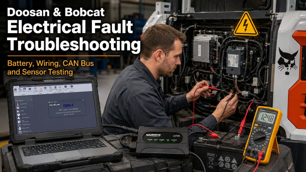
Doosan DMS-5 diagnostic software
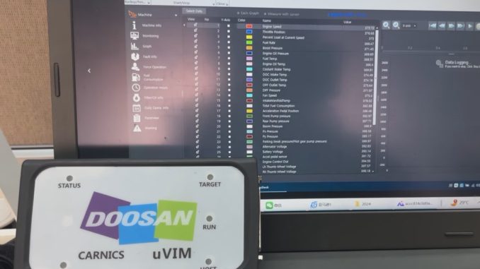
Doosan uVIM diagnostic interface
Bobcat diagnostic interface
Digital multimeter
Two-channel oscilloscope
CAN analyzer
Approved breakout or back-probe leads
Machine-specific wiring diagrams
ECU and sensor connector pinout information
Recommended Doosan DMS-5 Software
For supported Doosan equipment, DMS-5 Diagnostic Software can help technicians read fault codes, monitor controller data, view live sensor information, and verify repairs before replacing components.
Low or unstable system voltage can create misleading ECU, sensor, and CAN communication faults.
A machine may still crank or even start while the electrical supply is unstable enough to cause control modules to reset or disappear from the network.
Inspect the battery
Check:
Battery state of charge
Battery capacity
Battery terminals for looseness
Corrosion or oxidation
Battery cables
Engine and chassis grounds
Battery case for external damage
Where possible, check battery voltage not only at rest but also during cranking and under load.
Check for parasitic current draw.
Look for aftermarket equipment such as:
GPS trackers
Telematics devices
Radios
Cameras
Work lights
Auxiliary controllers
USB accessories
A device not installed by the original machine or engine manufacturer may cause excessive key-off current draw.
If the battery repeatedly becomes discharged while the machine is parked, perform a parasitic-current test after the controllers have entered sleep mode.
2. Inspect ECU, VCU and Sensor Connections
Construction equipment is exposed to vibration, moisture, oil, dust, heat, and repeated maintenance. Connector problems are therefore a common source of intermittent electrical faults.
Inspect connections at:
ECU
VCU
Sensors
Actuators
Engine harness
Machine harness
Diagnostic connector
CAN junctions
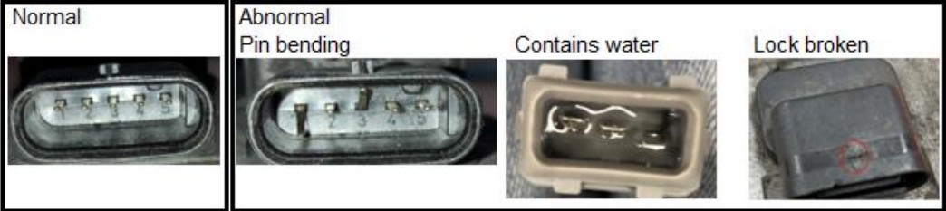
Inspect connector pins and terminals.
Look for:
Bent pins
Broken pins
Pushed-back terminals
Spread female terminals
Loose terminal tension
Corrosion
Water intrusion
Damaged seals
Broken connector locks
A connector may look normal but still have poor terminal contact.
Perform a Wiggle Test
With the diagnostic tool connected, monitor fault codes and relevant live data while gently moving the suspected connector or harness.
If an open-circuit fault appears or disappears while you move the wiring, inspect the terminal fit and harness more closely.
Many ECU inputs can detect open circuits with the key on, making this a useful test for intermittent contact problems.
3. Check for Cross-Connected Sensors
After an engine repair or wiring-harness replacement, similar connectors can occasionally be connected to the wrong sensors.
Check:
Connector location
Wire colors
Pin assignments
Sensor part numbers
Wiring diagrams
Do not assume a connector is correct simply because it fits.
A cross-connected sensor may still produce a believable electrical value while sending information from the wrong location.
4. Test Resistance-Type Sensors
Resistance testing is appropriate only for sensors designed to change resistance, such as some:
Coolant temperature sensors
Intake-air temperature sensors
Oil temperature sensors
Hydraulic temperature sensors
Pressure sensors, Hall-effect sensors, and many speed sensors normally require voltage or waveform testing instead.
Basic resistance test
Switch the machine off.
Disconnect the sensor.
Measure resistance directly across the specified terminals.
Compare the reading with the correct resistance-versus-temperature specification.
Result
Possible condition
Within specification
Sensor may be operating normally
OL / open circuit
Internal sensor break or wrong test pins
Near 0 Ω unexpectedly
Possible internal short
Incorrect for temperature
Sensor may be biased or defective
Reading changes when connector moves
Intermittent internal or terminal fault
Always compare the result with specifications for the exact sensor.
5. Check the Wiring Harness
If the sensor itself tests correctly, inspect the circuit between the sensor and ECU.
Check pin-to-pin continuity
Test:
Sensor Connector → ECU Connector
Check for:
Open circuit
Excessive resistance
Short to ground
Short to power
Short between circuits
Damaged shielding
Intermittent continuity
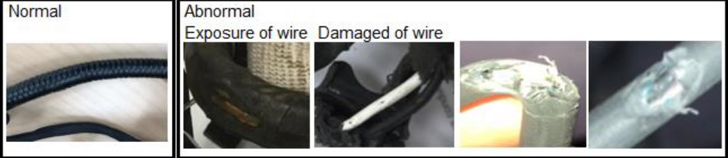
Also inspect the harness for:
Cuts
Broken wires
Crushing
Abrasion
Melted insulation
Pinched sections
Incorrect repairs
Damage near hot components
Pay particular attention to:
Engine-to-frame transition points
Cab hinges
Harness clamps
Connector entry points
Moving structures
Areas recently repaired
6. Check the CAN Network
If several unrelated controllers or sensors report communication faults, diagnose the CAN network before replacing individual components.
Typical CAN-related symptoms include:
Diagnostic tool cannot connect.
One or more ECUs are missing.
Multiple communication DTCs occur together.
Gauges or machine controls drop out.
Communication is intermittent
Faults change when you move the harness.
First Check: Can the Service Tool Communicate?
Determine whether:
No controllers communicate
Only one controller is offline.
Some controllers communicate intermittently.
Communication disappears during machine operation.
This helps separate a network-wide fault from a problem affecting only one branch or module.
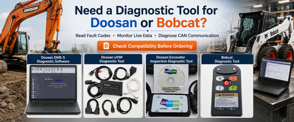
Doosan uVIM Diagnostic Tool
For supported Doosan machines, the Doosan uVIM Diagnostic Tool can be used with compatible diagnostic software to communicate with ECUs and VCUs, read faults, monitor live data, and check whether controllers remain online.
For Bobcat equipment, a compatible Bobcat Diagnostic Tool can help identify controller, sensor, and communication faults before manual circuit testing.
Many two-wire CAN networks use a 120-ohm terminating resistor at each end.
With two 120-ohm resistors connected in parallel, resistance between CAN High and CAN Low is typically approximately:
60 Ω
Perform resistance testing only with the network powered off and according to the applicable service procedure.
Resistance reading
Possible condition
Approximately 60 Ω
Both termination resistors likely connected
Approximately 120 Ω
One terminator or network section may be disconnected
Very low resistance
Possible CAN-H to CAN-L short or extra termination
Very high / OL
Open circuit or missing termination path
Reading changes when harness moves
Intermittent connector or wiring fault
Do not treat 60 Ω as a universal specification. Confirm the CAN topology for the actual machine first.
8. Check CAN High and CAN Low Voltage
The supplied Doosan/Bobcat troubleshooting information gives typical operating ranges of approximately:
CAN High: 2.5–3.5 V
CAN Low: 1.5–2.5 V
During communication, the signals should move in opposite directions.
A multimeter can provide a basic indication, but an oscilloscope is much better for identifying:
Electrical noise
Missing communication
Distorted edges
Reflections
Intermittent dropouts
Unequal CAN-H and CAN-L signals
9. Inspect CAN Signals With an Oscilloscope
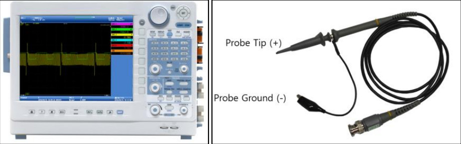
Use a two-channel oscilloscope where possible:
Channel 1 → CAN High
Channel 2 → CAN Low
A healthy differential CAN signal should show complementary movement:
When CAN High rises, CAN Low falls.
Look for:
Clean switching
Balanced signal timing
Excessive spikes
One line stuck high or low.
Missing activity
Distorted waveform shape
Abnormal amplitude
Possible causes include damaged termination resistors, wiring shorts, poor grounds, failed modules, corrosion, or poor harness repairs.
Use the correct diagnostic connector pinout to identify CAN High and CAN Low.
10. Check CAM and CRANK Signals
If the engine has:
No-start
Extended cranking
Intermittent shutdown
Synchronization faults
CAM sensor faults
CRANK sensor faults
Missing engine-speed signal
you may need to capture both signals simultaneously.
Required equipment
Prepare:
Two-channel oscilloscope
Appropriate probes
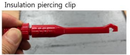
Approved breakout leads or piercing clips
Correct CAM/CRANK wiring information
Suggested oscilloscope settings
The supplied troubleshooting procedure specifies approximately:
Sampling interval/rate: 2 MHz
Input voltage range: ±30 V
Channels: at least 2
Channel 1: CAM
Channel 2: CRANK
Adjust settings as required to obtain a stable waveform.
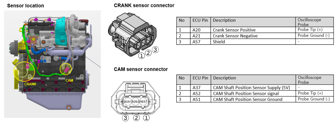
11. Identify CAM and CRANK Sensor Pins
Before connecting probes, identify:
Sensor supply
Sensor ground
CAM signal
CRANK signal
Never identify signal circuits only by wire color.
Use the wiring diagram and connector pinout for the exact engine.
Incorrect probing may short a reference-voltage or signal circuit.
12. Connect the Oscilloscope
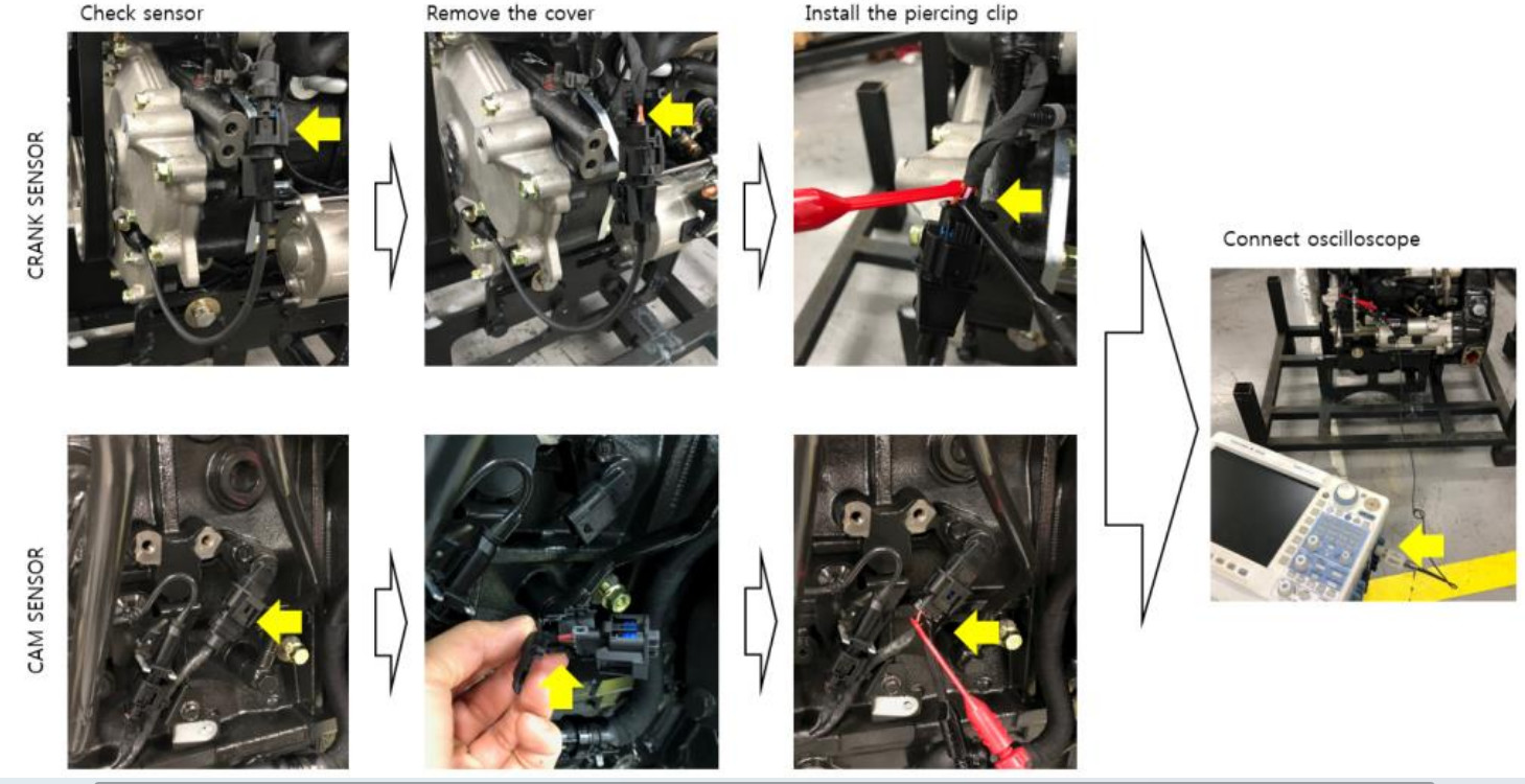
Where permitted by the service procedure:
Remove the connector or harness protection cover.
Connect a breakout lead or piercing clip to the CAM signal.
Connect the second probe to the CRANK signal.
Connect the oscilloscope grounds correctly.
Make sure no probe can contact an adjacent circuit.
Use a breakout harness whenever possible. Repeated insulation piercing can allow moisture to enter the conductor.
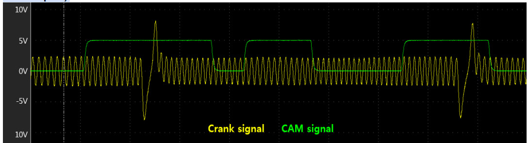
13. Measure CAM and CRANK Simultaneously
Crank or run the engine while recording both channels.
Don’t just confirm that both sensors generate a signal. Their timing relationship is also important.
Inspect:
Missing crank teeth
CAM rising edge
CAM falling edge
CAM-to-CRANK relationship
Signal amplitude
Signal stability
Intermittent dropouts
Electrical noise
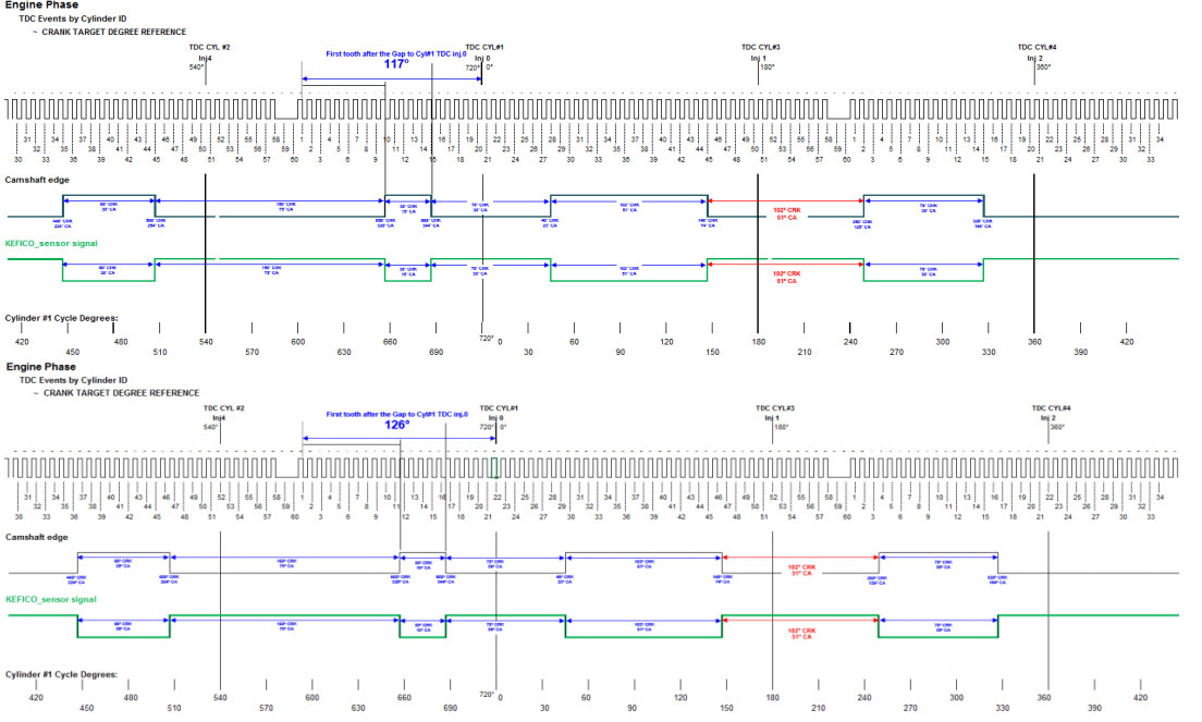
CAM/CRANK Synchronization
The original troubleshooting information references the following values:
DM01 / DM02: 117°
DM03: 126°
Focus on the crankshaft signal tooth position relative to the CAM rising and falling edges.
These values apply only to the engine families and specifications for which they were published. Do not use them as universal Doosan or Bobcat timing values.
Compare the measured waveform with the correct service specification or a known-good waveform.
An incorrect CAM/CRANK relationship can result from:
Mechanical timing error
Incorrect sensor installation
Damaged trigger wheel
Incorrect sensor air gap
Wrong sensor
Wiring problem
Signal distortion
Internal engine timing problem
Practical Diagnostic Decision Tree
Multiple unrelated electrical codes
Start with:
Battery → Grounds → Controller Power → CAN Network
Do not replace several sensors at once.
One sensor has an open-circuit fault.
Check:
Connector → Wiggle Test → Supply/Ground → Wiring → Sensor
One ECU is missing from the diagnostic network.
Check:
ECU Power → Ground → CAN-H/CAN-L → Connector → ECU
All controllers are offline.
Check:
Battery → Main Fuse → Diagnostic Connector → CAN Resistance → Network Short
Engine cranks but does not start.
Check:
Engine RPM → CRANK Signal → CAM Signal → CAM/CRANK Synchronization
Common Diagnostic Mistakes
Replacing the ECU too early
Verify power, grounds, connectors, and CAN communication before suspecting the ECU itself.
Replacing a sensor based only on the fault code
A sensor code may actually be caused by:
Broken wiring
Poor ground
Missing reference voltage
Loose terminals
Connector corrosion
Ignoring battery condition
Low voltage can produce several communication and sensor faults at the same time.
Checking continuity only
A wire may pass an unloaded continuity test but fail under electrical load.
Use voltage-drop testing where appropriate.
Ignoring terminal tension
A connector terminal can look clean but still make poor contact.
Treating 60 Ω as universal
Approximately 60 Ω is common on two-terminator CAN networks, but verify the actual machine topology.
Testing CAM and CRANK separately
For synchronization diagnosis, capture both signals simultaneously.
Final Verification After Repair
After completing the repair:
Reconnect all connectors.
Confirm stable battery voltage.
Connect the diagnostic tool.
Clear applicable fault codes.
Cycle machine power if required.
Start the engine.
Confirm that the original fault does not return.
Monitor relevant live data.
Wiggle the repaired harness area.
Confirm stable CAN communication.
Operate the machine under the condition that originally caused the fault.
Perform a final diagnostic scan.
If the problem was intermittent, do not consider the repair complete simply because the fault code can be cleared.
Frequently Asked Questions
Why does my Doosan or Bobcat machine show several electrical fault codes at the same time?
Multiple unrelated faults often indicate a shared problem such as low battery voltage, poor grounding, loss of controller power, or CAN network failure rather than multiple defective sensors.
What resistance should CAN High to CAN Low measure?
On a conventional network using two 120-ohm termination resistors, you should typically measure about 60 Ω with power off. Always verify the exact network design first.
What voltage should CAN High and CAN Low show?
The supplied procedure lists approximately 2.5–3.5 V for CAN High and 1.5–2.5 V for CAN Low during communication.
Can a weak battery cause CAN communication faults?
Yes. Low or unstable voltage can cause ECUs to reset or temporarily disappear from the network.
Should I replace a sensor when the ECU reports an open circuit?
Not immediately. First check the connector, reference voltage, ground, signal wire, terminal contact, and harness continuity.
How do I diagnose an intermittent wiring fault?
Monitor the relevant DTC or live-data value while gently moving the connector and wiring harness. If the fault appears or disappears, inspect that area closely.
When should I use an oscilloscope?
An oscilloscope is particularly useful for:
CAN waveform problems
CAM/CRANK synchronization
Intermittent sensor signals
Electrical noise
Signal distortion
Faults that cannot be confirmed with a multimeter
Which diagnostic tools can be used on Doosan and Bobcat machines?
Tool requirements depend on machine generation and controller type. Supported Doosan equipment may use DMS software with a compatible interface such as uVIM, while Bobcat equipment requires a compatible Bobcat diagnostic platform.
Recommended Doosan & Bobcat Diagnostic Tools
Before replacing an ECU, sensor, or wiring harness, use the correct diagnostic platform to identify the fault and monitor controller data.
DOOSAN DMS-5 Diagnostic Software
For supported Doosan equipment, DMS-5 provides diagnostic functions to read fault codes, monitor, and troubleshoot.
For supported Bobcat skid-steer loaders, excavators, and other machines, the Bobcat diagnostic kit can assist with fault-code, controller, sensor, and communication diagnosis.
Begin with the power supply and grounds because voltage problems can produce several misleading symptoms at once. Inspect connectors and wiring before replacing sensors or controllers. When multiple modules lose communication, diagnose the CAN network. For synchronization or no-start problems, capture CAM and CRANK waveforms simultaneously and compare them with the correct engine specification.
A structured diagnostic process takes a little more time initially, but usually reduces unnecessary parts replacement and repeat repairs.
Leave a Reply