Correct static injection timing is essential for Cummins M11 engine performance, fuel efficiency, combustion quality, and emissions control. Inspect static timing after an engine overhaul or whenever gear train components have been removed, replaced, disassembled, or reinstalled.
This guide explains how to inspect the static injection timing of a Cummins M11 Series engine using Cummins injector timing tool Part No. 3823451.
Important: Injection timing specifications may vary according to the engine CPL number. Always verify the final measurement against the applicable Cummins Control Parts List and service documentation.
What Is Static Injection Timing?
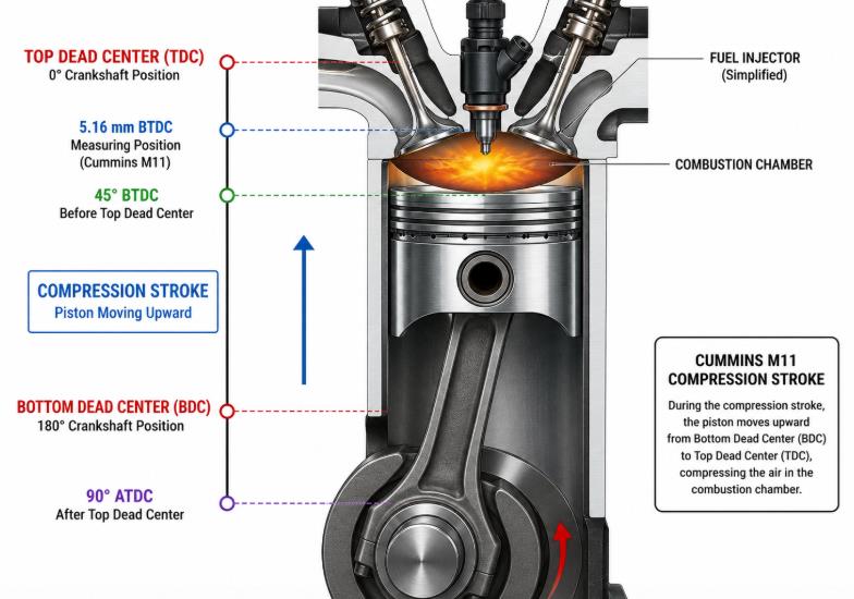
Static injection timing shows when fuel injection begins during the compression stroke.
On the Cummins M11 Series engine, the timing inspection is performed when the No. 1 piston is positioned 5.16 mm before top dead center, or BTDC, on the compression stroke.
At this piston position, measure the remaining injector pushrod travel with injector timing tool Part No. 3823451. Compare the resulting measurement with the specification assigned to the engine’s CPL number.
When Should Static Injection Timing Be Checked?
Inspect the static injection timing:
After a complete engine overhaul
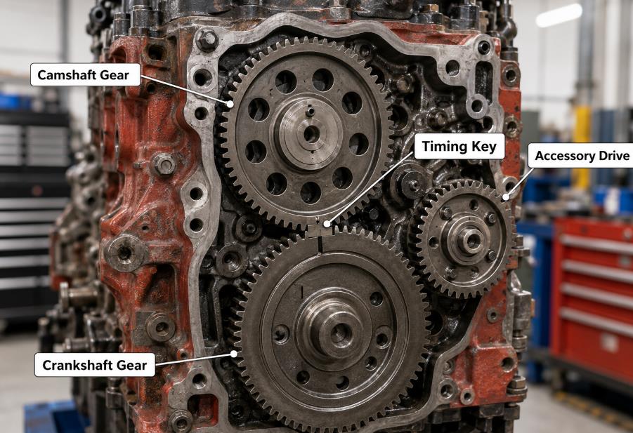
After removing or replacing the camshaft gear
After servicing the accessory drive or gear train
After disassembling or reinstalling timing-related components
When incorrect injection timing is suspected
Required Tool
Use the following special tool:
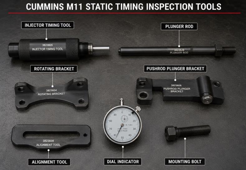
Cummins injector timing tool, Part No. 3823451
Dial indicator
Pushrod plunger bracket
Alignment tool
Suitable hand tools for rotating the accessory drive shaft
Diagnose the Cummins M11 Before Adjusting Injection Timing
Static injection timing is a mechanical measurement, but electronic diagnosis should also be completed before disassembling or adjusting the engine gear train.
Monitor engine speed, temperature, pressure, and sensor data
Check ECM information and calibration details
Perform diagnostic tests supported by the connected engine
Record engine operating data before and after repairs
This helps determine whether poor performance is caused by incorrect mechanical timing, an electronic control problem, a sensor fault, or another fuel-system issue.
Important: A Cummins diagnostic adapter does not replace injector timing tool Part No. 3823451. The mechanical timing tool and dial indicator are still required to measure static injection timing.
Recommended Cummins Diagnostic Solution
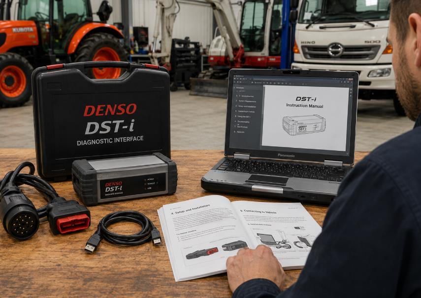
For workshops servicing Cummins M11 and other electronically controlled Cummins engines, a professional diagnostic kit can provide faster access to ECM fault information and live operating data.
Suggested product features:
Compatible Cummins diagnostic interface
Support for Cummins INSITE diagnostic software
Engine fault-code reading and clearing
Live-data monitoring
ECM identification and calibration information
Suitable for truck, bus, construction, and industrial engine service
[View Cummins Diagnostic Tools and INSITE Solutions →]
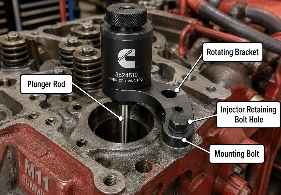
Insert plunger rod 1 of injector timing tool Part No. 3823451 into the No. 1 cylinder injector bore, as shown in Figure 2-265.
Next, align rotating bracket 2 with the injector retaining bolt hole, as shown in Figure 2-266. Install the mounting bolt through the rotating bracket.
Tighten bolt 3 enough to secure the tool, but do not overtighten it. Refer to Figure 2-267.
2. Align the Pushrod Plunger
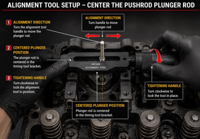
Position the pushrod plunger bracket behind the center bracket of the timing tool, as shown in Figure 2-268.
Use the alignment tool to center the pushrod plunger rod. When the rod is correctly centered, tighten the handle and remove the alignment tool, as shown in Figure 2-269.
3. Install the Injector Pushrod
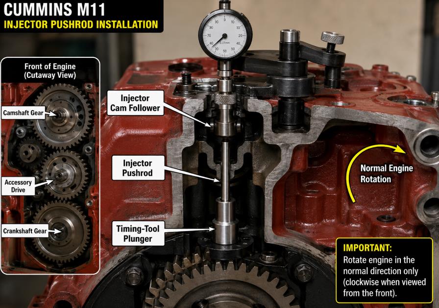
Install the injector pushrod between the injector cam follower and the timing-tool plunger, as shown in Figure 2-270.
Then rotate the accessory drive shaft clockwise, in the normal direction of engine rotation, to locate top dead center on the compression stroke. Refer to Figure 2-271.
For an accurate static timing measurement, rotate the crankshaft only through the accessory drive shaft during this inspection.
4. Set the Dial Indicator at Top Dead Center
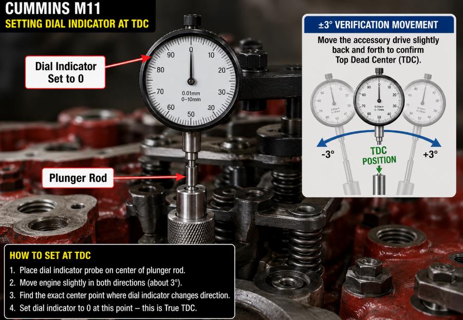
Place the dial indicator probe in the center of the plunger rod.
Move the dial indicator downward until it is within 0.63 mm of its fully compressed position, as shown in Figure 2-272.
As the plunger rod moves upward toward top dead center, adjust the dial indicator to zero. Refer to Figure 2-273.
Move the accessory drive shaft slightly backward and forward, approximately three degrees on either side of the zero position. This confirms the exact top-dead-center position, as shown in Figure 2-274.
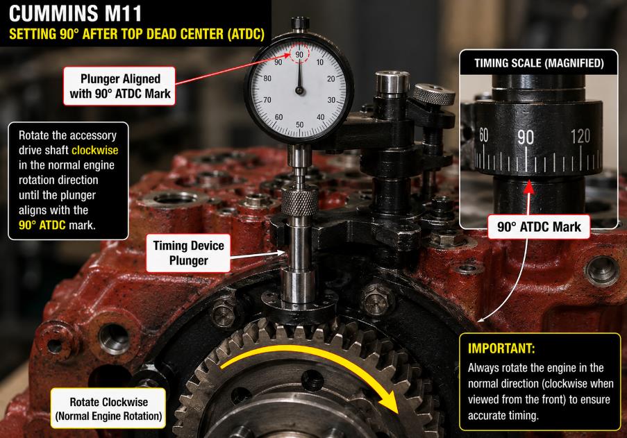
5. Position the Engine at 90 Degrees After TDC
Rotate the accessory drive shaft clockwise until the crankshaft reaches 90 degrees after top dead center, or ATDC.
The plunger should align with the 90-degree mark on the timing device, as shown in Figure 2-275.
6. Reset the Dial Indicator
Place the dial indicator probe at the center of the plunger rod again.
Move the dial indicator downward until it is within 0.63 mm of the fully compressed position. Adjust the indicator to zero, as shown in Figure 2-276.
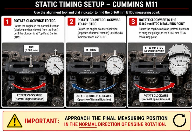
7. Remove Gear Train Backlash
Rotate the accessory drive shaft clockwise to top dead center.
Then rotate the accessory drive shaft counterclockwise until the crankshaft reaches 45 degrees before top dead center, as shown in Figure 2-277.
This step removes gear train backlash and helps ensure an accurate measurement.
If the crankshaft moves past the required 5.160 mm BTDC position, rotate it counterclockwise back to 45 degrees BTDC. Then rotate the accessory drive shaft clockwise again until the dial indicator reads 5.160 mm BTDC.
Always approach the measuring position in the normal clockwise direction of engine rotation.
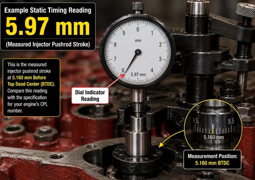
8. Read the Static Injection Timing
Read the dial indicator counterclockwise from the zero position.
The measured pushrod stroke is the engine’s static injection timing value. In the example shown in Figure 2-278, the measured static injection timing is 5.97 mm, which is then compared with the Cummins specification.
Record the measurement for comparison with the Cummins specification.
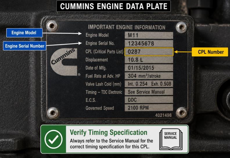
Verify the Timing Specification Using the CPL Number
Locate the CPL number on the engine data plate.
Compare the measured timing value with the specification listed for that CPL in the Cummins Control Parts List (Part No. 3379133) or the applicable Cummins M11 service information.
Do not assume that one timing specification applies to every M11 engine. Fuel system calibration and timing requirements may differ by CPL configuration.
How to Interpret the Dial Indicator Reading
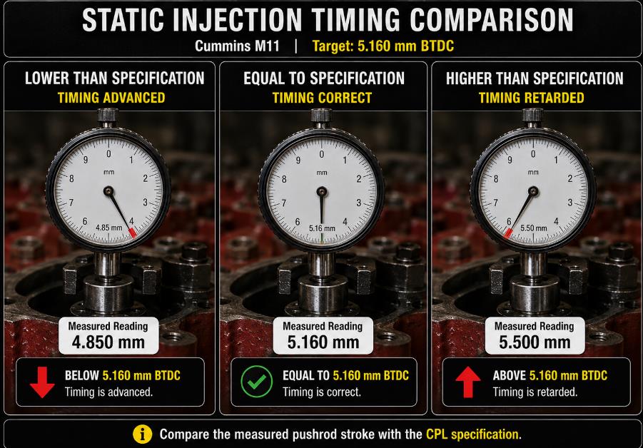
Compare the measured value with the specified static injection timing value:
A reading higher than the specification indicates that the injection timing is retarded.
A reading lower than the specification indicates that the injection timing is advanced.
Refer to Figure 2-279 for the timing comparison.
How Static Injection Timing Is Adjusted
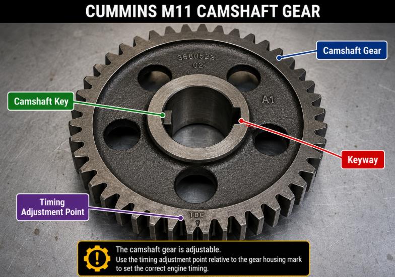
If the measured timing is outside the Cummins specification, static injection timing can be changed by removing the camshaft gear and installing the appropriate camshaft timing key, as shown in Figure 2-280.
Because changing the camshaft key directly affects injection timing and engine operation, base the correct key selection on the measured timing error and the applicable Cummins service specifications.
Final Inspection Notes
Before returning the engine to service, confirm that the No. 1 piston was measured on the compression stroke.
Confirm that gear train backlash was removed before taking the measurement.
Verify that the crankshaft approached the measuring position in the normal direction of rotation.
Compare the result with the correct CPL specification.
Recheck the timing after changing the camshaft key or disturbing any gear train components.
Accurate static injection timing helps the Cummins M11 engine achieve proper combustion, reliable performance, improved fuel economy, and controlled exhaust emissions.

Leave a Reply