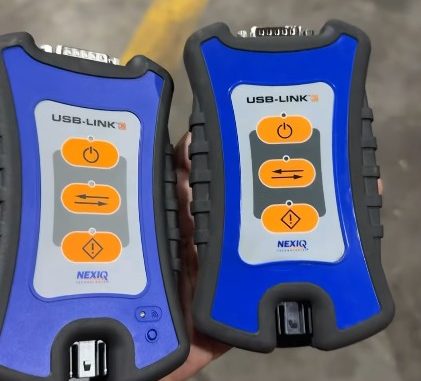
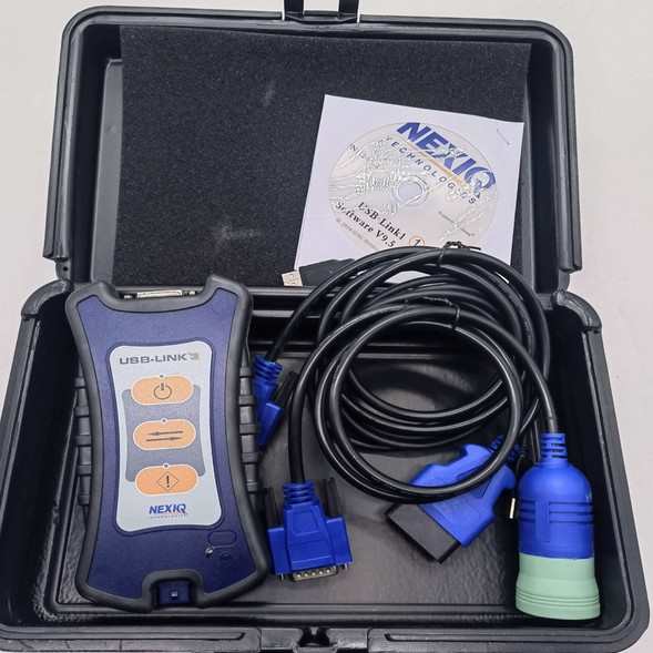
The NEXIQ USB-Link 3 Wired NQ121054 connects a Windows PC to commercial-vehicle diagnostic networks through USB.
If it powers on but will not communicate, troubleshoot the connection in four stages:
PC → USB-Link 3 → vehicle network → diagnostic software/ECU
This approach helps avoid replacing the interface when the real problem is a driver, cable, diagnostic connector, network, ECU, or software configuration issue.
What Is the NEXIQ USB-Link 3 Wired?
The NQ121054 is the wired USB version of the USB-Link 3.
It supports multiple commercial-vehicle communication technologies, including J1939, CAN, CAN FD, J1708, DoIP, ISO 15765, and other supported networks.
However, protocol support does not guarantee support for every vehicle, ECU, programming function, or OEM application.
If programming an ECU, follow the OEM battery-support requirements and use a stable wired USB connection.
Driver Installation
Install the correct NEXIQ USB-Link 3 driver before normal use.
Recommended procedure:
Close diagnostic software.
Disconnect other diagnostic interfaces.
Install the USB-Link 3 driver with administrator rights.
Restart Windows if required.
Connect the interface directly to the PC.
Confirm that NEXIQ Device Tester detects it.
Do not install drivers intended for a different USB-Link version or an aftermarket interface.
How to Connect the USB-Link 3
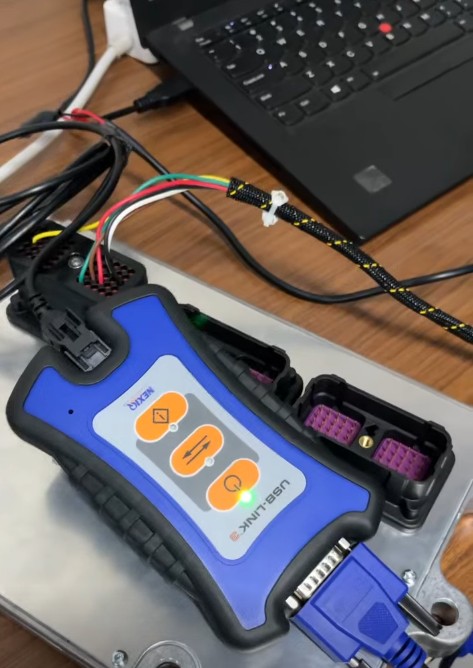
A practical wired setup is:
Connect USB-Link 3 to the computer.
Connect the vehicle cable to the interface.
Connect the cable to the vehicle diagnostic port.
Turn the ignition on if required.
Open NEXIQ Device Tester.
Select the correct interface and protocol.
If Device Tester communicates, the basic PC-to-vehicle connection is working.
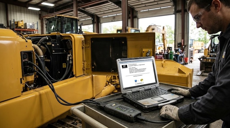
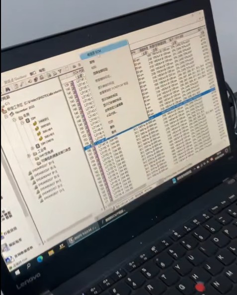
Use Device Tester Before OEM Software
Device Tester helps separate hardware/network faults from software configuration problems.
Select:
Driver: USB-Link 3
Device: USB-Link 3, USB
Protocol: the vehicle’s actual communication protocol
If vehicle messages appear, the interface and basic vehicle network are communicating.
If Device Tester works but the OEM software does not, check the application’s RP1210 or VCI settings.
Common USB-Link 3 Problems
Symptom
Likely Area to Check
PC does not detect interface
Driver, USB cable, USB port
Power LED off
Vehicle connector power, ground, fuse
Power on but no communication
Protocol, cable, vehicle network
Device Tester works but software fails
RP1210/VCI settings
One ECU missing
ECU power, network branch, gateway
Communication is intermittent
Cable, connector, USB port
Programming disconnects
Voltage stability, USB connection, driver
USB-Link 3 Not Detected by Windows
Check:
correct driver installed
direct USB connection instead of a hub
another USB port
known-good USB cable
Windows power-management settings
If another USB port or cable fixes the problem, the VCI itself may be fine.
Power LED Does Not Turn On
If the interface does not power up from the vehicle:
Check the diagnostic connector.
Check the diagnostic-port fuse.
Verify battery positive and ground.
Inspect for bent or pushed-back terminals.
Test another vehicle cable if available.
Don’t assume the interface has failed until you confirm vehicle-side power.
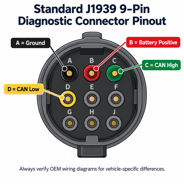
J1939 9-Pin Connector Checks
On a standard J1939 9-pin connector:
Pin
Typical Function
A
Ground
B
Battery positive
C
CAN High
D
CAN Low
A common mistake is assuming battery positive is “pin 9.” On a standard J1939 Deutsch connector, battery positive is normally cavity B.
Always verify the OEM wiring diagram because some equipment uses different connector arrangements.
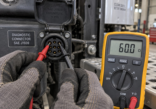
CAN Resistance Check
On many conventional CAN networks, resistance between CAN High and CAN Low is approximately 60 Ω with vehicle power off.
Typical interpretations:
around 60 Ω: normal two-terminator network
around 120 Ω: possible missing terminator or open branch
very low resistance: possible short
open circuit: possible wiring break
Do not treat 60 Ω as a universal rule. Gateway and OEM-specific network designs can produce different readings.
Device Tester Works but OEM Software Does Not
If Device Tester communicates successfully, check the diagnostic software configuration.
Common causes include:
wrong RP1210 interface selected
incorrect vehicle family
unsupported software/interface combination
expired license or required authorisation
incorrect communication settings
This usually indicates a software-side issue rather than a vehicle wiring fault.
Some ECUs Communicate, but One Does Not
If the engine ECU communicates but ABS, transmission, or another controller does not, the interface is probably not the primary problem.
Check:
ECU fuse
ECU power and ground
CAN branch wiring
gateway communication
module wake-up conditions
software compatibility
One missing ECU usually points to a module or network-branch problem.
Intermittent Communication
If communication drops randomly:
gently move the USB and vehicle cables
connect directly to the laptop
try another cable
try another USB port
test on another known-good vehicle
Change one component at a time so you can identify the actual failure.
ECU Programming Precautions
For ECU programming:
use a wired USB connection
stabilise vehicle voltage
keep the laptop powered
prevent sleep or restart
avoid moving diagnostic cables
verify ECU identification before programming
If programming repeatedly fails at the same stage, investigate the software package, ECU state, vehicle power, and OEM recovery procedure instead of retrying the flash.
RP1210 vs J2534
Heavy-duty diagnostic applications commonly use RP1210.
If Device Tester works but the truck diagnostic application does not, verify that you selected the correct RP1210 USB-Link 3.
Some pass-through diagnostic and programming applications use J2534.
Do not assume USB-Link 3 is a universal J2534 programming device. Programming support depends on the specific vehicle and software.
Scan Tools Cannot Confirm Every Fault.
A communication interface can read DTCs and live data, but scan data alone cannot confirm every mechanical problem.
Some faults still require:
multimeter testing
oscilloscope testing
fuel or hydraulic pressure measurement
smoke testing
mechanical inspection
OEM wiring diagrams
Use scan data to guide physical testing.
Active vs Stored Faults
An active fault is currently detected.
A stored or inactive fault occurred previously and may no longer be present.
After repair:
clear the fault if appropriate
operate the vehicle under similar conditions
rescan the system
verify live data
Confirm the fault does not return
Clearing a code alone does not prove the repair was successful.
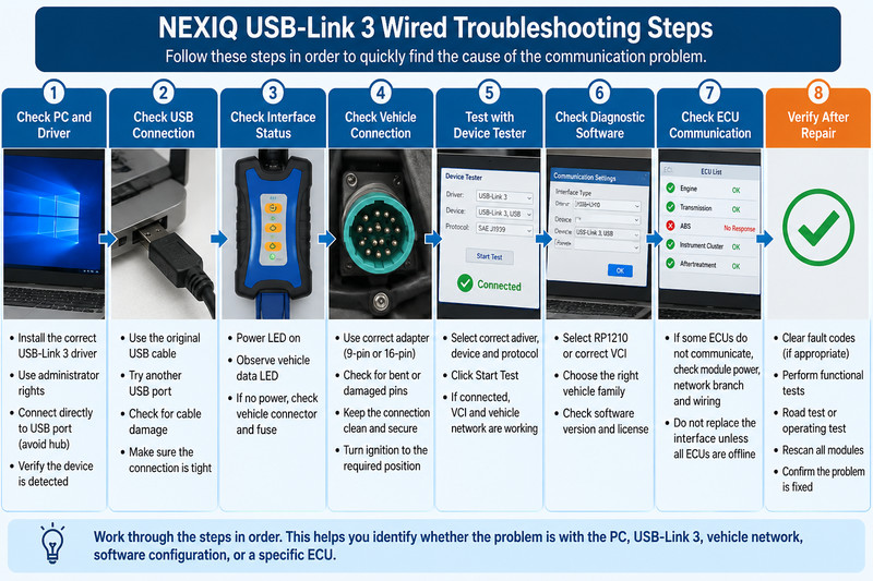
Recommended Troubleshooting Order
When USB-Link 3 will not communicate, follow this sequence:
Verify the exact interface and driver.
Confirm Windows detects the interface.
Check vehicle-side power and ground.
Select the correct protocol.
Test communication with Device Tester.
Check OEM software RP1210/VCI settings.
Diagnose missing ECUs individually.
Perform a final scan after repair.
This sequence quickly separates interface problems from vehicle network, ECU, or software configuration faults.
Need a Heavy-Duty Truck Diagnostic Interface?
If you need a wired diagnostic interface for heavy-duty truck troubleshooting, Obdii.shop also offers a NEXIQ 3 USB Link compatible diagnostic interface for use with supported truck diagnostic applications.
Before ordering, confirm your vehicle, diagnostic software, Windows system, required protocol, and function compatibility. This product uses its own specified driver and setup requirements, so do not install genuine NEXIQ USB-Link 3 firmware or drivers unless the hardware instructions specifically require them.
Compatibility tip: If you are unsure whether the interface will work with your truck or diagnostic software, check compatibility before purchase rather than assuming that RP1210, J1939, or J2534 support guarantees every diagnostic function.
FAQ
Why does USB-Link 3 power on but not communicate?
Power only confirms that the interface is receiving voltage. Check the protocol, diagnostic cable, ignition state, and vehicle network.
Why does Device Tester work but my diagnostic software does not?
The most likely causes are incorrect RP1210/VCI selection, software compatibility, vehicle selection, or licensing.
Can USB-Link 3 be used for ECU programming?
It can be used with supported applications, but actual programming capability depends on the vehicle, ECU, software, interface API, and required OEM authorisation.
Why can I communicate with the engine ECU but not another module?
Check the missing module’s power, ground, network branch, gateway, and software support before replacing the interface.
Should J1939 always measure 60 ohms?
No. Approximately 60 Ω is common on conventional CAN networks, but OEM network architecture can produce different readings.
Leave a Reply