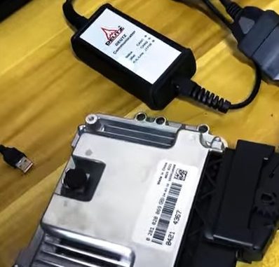
Deutz EMR3 fault code 94 / SPN 523239 / FrmMngDecV1 means the engine ECU is not receiving a valid DEC-V1 CAN message, also described as the pseudo-pedal message.
The fault may be caused by missing CAN communication, an invalid demand value, damaged network wiring, loss of power to the transmitting controller, or incorrect controller parameterization.
Important: CAN topology, connector pinouts, expected resistance, and parameter settings vary by machine. Use the wiring diagram and service documentation for the exact engine and equipment configuration.
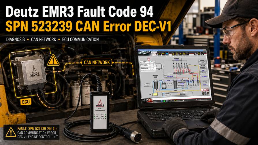
Fault Code Summary
| Item | Details |
| Deutz error code | 94 |
| SPN | 523239 |
| Blink code | 5-2-6 |
| Fault identifier | FrmMngDecV1 |
| Message | DEC-V1 pseudo-pedal |
| Main condition | Message missing or value outside the expected range |
| Warning lamp | Permanently illuminated |
| System response | Warning and substitute-value operation |
| Self-healing | Yes |
| Signal priority | 1 |
Required Diagnostic Equipment
- Deutz DECOM diagnostic interface
- Compatible Deutz SerDia software
- Windows diagnostic laptop
- Machine-specific wiring diagram
- Digital multimeter
- CAN breakout leads or approved test adapters
- Oscilloscope or CAN analyzer, when available
- Deutz SerPic parts information, if component identification is required
Use a SerDia version that supports the installed EMR3 controller.
What Does the Fault Mean?
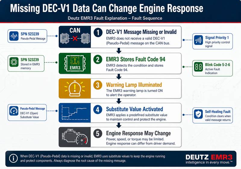
The EMR3 ECU communicates with other machine controllers through the CAN network. The DEC-V1 message provides an electronically generated engine-demand value, sometimes called a pseudo-pedal signal.
Depending on the application, the message may come from a:
- Vehicle or machine controller
- Transmission controller
- Application controller
- Remote throttle controller
- Electronic accelerator module
The fault is stored when the message is missing, delayed, invalid, or outside the permitted range. This does not automatically mean that the EMR3 ECU or accelerator pedal is defective.
Possible FMI Values
| FMI | Meaning |
| FMI 12 | Defective component |
| FMI 2 | Erratic, intermittent, or incorrect data stream |
Record the FMI shown in SerDia because it can help distinguish a component problem from a communication-data fault.
System Reaction
When the fault is active, the system may:
- Illuminate the warning lamp continuously.
- Store the event in error memory.
- Replace the missing input with a substitute value.
- Change engine response according to the customer configuration
The engine may continue running, but accelerator response or available performance may be affected.
Most Likely Causes
Common causes include:
- Transmitting controller offline or without power
- CAN High and CAN Low reversed
- Open circuit in the CAN harness
- Short between CAN High and CAN Low
- Short to power or ground
- Loose, damaged, or corroded terminals
- Incorrect CAN termination
- Damaged twisted-pair wiring
- Defective transmitting controller
- Invalid input to the transmitting controller
- Incorrect software or parameter configuration
- Mismatched replacement ECU settings
- Related CAN communication faults
Diagnostic Procedure
1. Confirm the Fault With SerDia
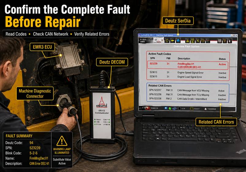
Connect the Deutz DECOM interface and establish communication with the EMR3 ECU.
Confirm:
Deutz Error 94 — SPN 523239 — FrmMngDecV1
CAN Error DEC-V1
Before clearing the code, record:
- FMI
- Active or stored status
- Occurrence count
- Engine operating hours
- Battery voltage
- Engine speed and load
- Related CAN faults
- Operating conditions when the fault occurred
An inactive code may indicate an intermittent connector, wiring, or controller-power problem.
2. Scan the Other Controllers
Do not diagnose only the EMR3 ECU. Check all available controllers on the machine network, especially the unit responsible for sending DEC-V1.
Look for faults involving:
- Controller power supply
- CAN communication
- Accelerator or demand input
- Missing messages
- Internal controller errors
- Incorrect configuration
A code in the transmitting controller may identify the root cause more directly.
3. Identify the DEC-V1 Transmitter
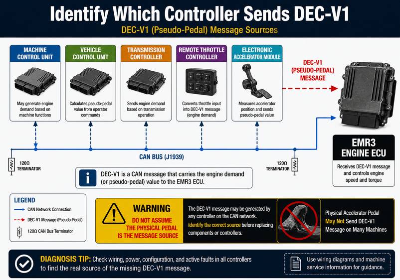
Use the wiring diagram and controller documentation to determine which module sends the pseudo-pedal message.
Do not replace the physical accelerator pedal based only on the term “pseudo pedal.” On many machines, the demand value is calculated and transmitted by another electronic controller.
4. Check Transmitter Power and Ground
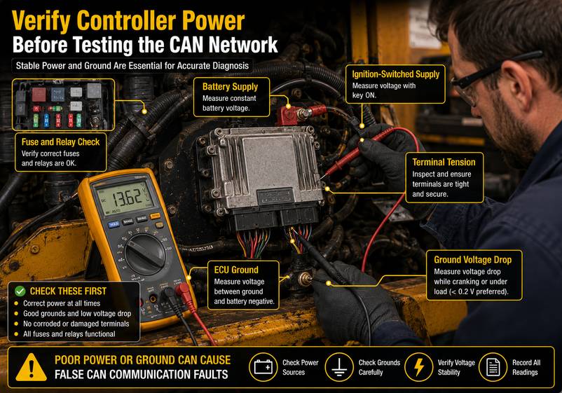
Verify:
- Battery supply
- Ignition-switched supply
- Fuses and relays
- Ground connections
- Ground voltage drop
- Connector condition
- Terminal tension
A controller that loses power will stop transmitting its CAN messages even when the network wiring is intact.
5. Inspect the CAN Harness

With the system switched off, inspect:
- CAN High and CAN Low wiring
- Twisted-pair condition
- Connector locks and seals
- Corrosion or moisture
- Crushed or abraded sections
- Aftermarket splices
- Routing near heat or moving components
- Recently repaired areas
Check engine-to-chassis and cab-harness transition points carefully because these areas are exposed to vibration and movement.
6. Verify CAN Polarity
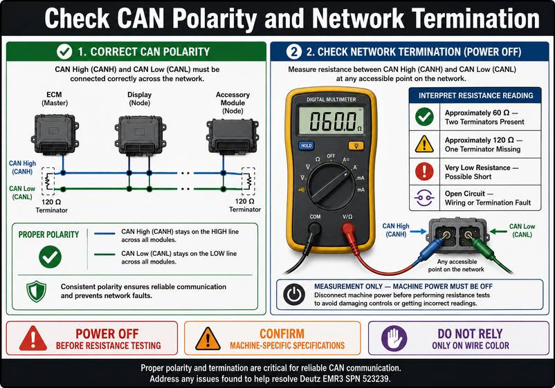
Confirm that CAN High and CAN Low are connected to the correct terminals throughout the network.
Reversed polarity may prevent communication or cause intermittent faults. Use the wiring diagram rather than relying only on wire colors.
7. Test for Opens and Shorts
With the network powered off and modules disconnected as required, check for:
- Open CAN High circuit
- Open CAN Low circuit
- Short between CAN High and CAN Low
- Short to ground
- Short to battery voltage
- Excessive connector or splice resistance
Do not perform resistance testing on a powered circuit.
8. Check Network Termination
Many CAN networks use two 120-ohm terminating resistors. In that configuration, resistance measured between CAN High and CAN Low with power off is normally close to 60 ohms.
| Reading | Possible condition |
| Approximately 60 ohms | Both terminators likely connected |
| Approximately 120 ohms | One terminator or network section missing |
| Very low resistance | Short circuit or extra termination |
| Very high/open | Broken circuit or missing termination |
| Unstable reading | Intermittent wiring or connector fault |
Confirm the correct expected value for the specific machine before making a repair decision.
9. Check the CAN Signal
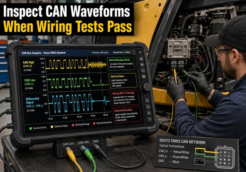
When available, use an oscilloscope or CAN analyzer to look for:
- Normal differential switching
- Missing message activity
- Distorted waveforms
- Excessive electrical noise
- Incorrect bus voltage
- Communication changes when the harness is moved
Use approved breakout leads to avoid damaging ECU terminals.
10. Check the Transmitting Controller
Confirm that the controller sending DEC-V1:
- Communicates normally
- Receives valid demand inputs
- Produces a plausible pseudo-pedal value
- Transmits the message at the expected rate
- Has no internal fault codes
- Uses the correct software and parameter set
An invalid sensor or switch input may cause the controller to transmit an out-of-range DEC-V1 value even when the CAN network is operating correctly.
11. Verify Parameterization
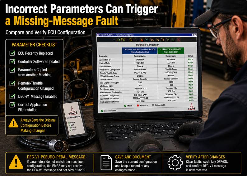
Check whether the fault began after:
- ECU replacement
- Machine-controller replacement
- Software update
- Engine installation change
- Parameter copying
- Remote-throttle modification
- Harness or attachment replacement
Incorrect parameters may cause the EMR3 ECU to expect a message that is not configured on the machine.
Record the original parameter values before making changes.
12. Check for Intermittent Wiring
Monitor DEC-V1 status while gently moving the harness at:
- Connector entry points
- Sharp bends
- Mounting brackets
- Cab hinges
- Engine-to-frame transitions
- Recently repaired sections
If the fault appears during movement, inspect for a broken conductor or loose terminal.
Diagnostic Results
| Finding | Recommended action |
| Transmitter offline | Check power, ground, fuses, relays, and CAN connection |
| Multiple CAN faults | Diagnose the common network problem first |
| CAN polarity reversed | Correct the wiring and retest |
| Open or short found | Repair the harness using an approved method |
| Incorrect termination | Inspect network branches and terminating resistors |
| DEC-V1 absent with transmitter powered | Test the transmitting controller and configuration |
| DEC-V1 value implausible | Check controller inputs and parameterization |
| Internal transmitter fault confirmed | Repair or replace the transmitting controller |
| Fault started after ECU replacement | Verify software and application parameters |
Repair Recommendations
Depending on the test results, repair may involve:
- Restoring controller power or ground
- Repairing CAN wiring
- Replacing damaged terminals or connectors
- Correcting CAN High and CAN Low polarity
- Restoring network termination
- Correcting controller parameters
- Repairing the demand-input circuit
- Replacing the transmitting controller after wiring and configuration checks
When repairing CAN wiring, maintain the correct twisted-pair structure and avoid long untwisted sections or low-quality splices.
Clear the Fault and Verify the Repair
After completing the repair:
- Reconnect all controllers and connectors.
- Switch on control power.
- Connect Deutz DECOM and SerDia.
- Clear the EMR3 error memory.
- Clear related faults from other controllers.
- Restart the machine.
- Confirm all controllers communicate.
- Monitor the DEC-V1 value.
- Operate the engine through the relevant speed and load range.
- Confirm code 94 does not return.
- Perform a final system scan.
- Save the diagnostic report.
Because the fault is self-healing, it may become inactive after communication is restored. The underlying cause should still be identified and corrected.
Final Verification Checklist
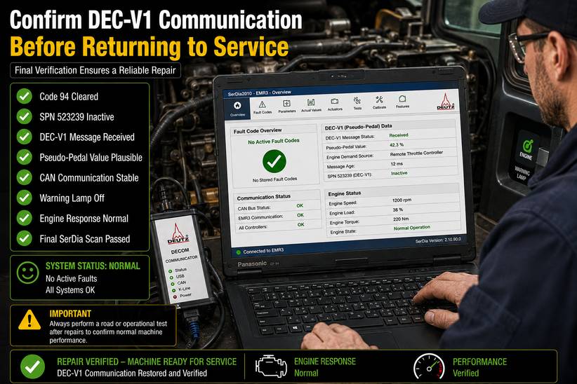
Before returning the machine to service, confirm:
- Code 94 and SPN 523239 are inactive.
- DEC-V1 messages are received consistently
- The pseudo-pedal value is plausible.
- No related CAN faults remain.
- Power and grounds are stable.
- Parameter settings match the machine.
- Engine response is normal.
- The warning lamp remains off.
- The final SerDia scan passes.
Frequently Asked Questions
What does Deutz fault code 94 mean?
It means the EMR3 ECU is not receiving a valid DEC-V1 pseudo-pedal CAN message, or the received value is outside the expected range.
What is SPN 523239?
SPN 523239 identifies the FrmMngDecV1 communication fault in this Deutz EMR3 application.
What is the DEC-V1 pseudo-pedal message?
It is an engine-demand value transmitted over CAN by another machine controller. The exact sender depends on the equipment configuration.
Can damaged CAN wiring cause this fault?
Yes. Open circuits, shorts, reversed polarity, incorrect termination, corrosion, and loose connections can interrupt DEC-V1 communication.
Can incorrect parameters trigger the fault?
Yes. The ECU may expect the wrong message or interpret the transmitted value incorrectly if the parameter configuration does not match the machine.
Which diagnostic tool is required?
A Deutz DECOM interface with compatible Deutz SerDia software can be used to read the fault, monitor the system, and verify the repair.
Conclusion
Deutz EMR3 fault code 94 / SPN 523239 / FrmMngDecV1 indicates that the ECU cannot receive or validate the DEC-V1 pseudo-pedal message.
Begin by identifying the transmitting controller, then inspect its power supply, CAN wiring, connectors, network termination, input signals, and parameter configuration. Do not replace the engine ECU or pedal assembly until the communication network and message source have been tested.
After repair, clear the error memory, monitor DEC-V1 in SerDia, operate the machine under normal conditions, and confirm that the warning lamp remains off and the fault does not return.
More information about Deutz case, please refer to Deutz trouble repair
Leave a Reply